Maintenance, Tips, How-Tos
Photo Tutorials Will Be Added On An Ongoing Basis
Scroll Down The Page To Find What You're After, In The Order Shown:
1 • Carb Fuel Joint O-ring & Fuel Line Replacement (1986-97)
2 • Rear Caliper Sleeve Replacement ('86-87)
3 • Master Cylinder Rebuild
4 • Sight Glass Replacement
5 • Carburetor Bowl Gasket Replacement
6 • Fuel Tank Sealing
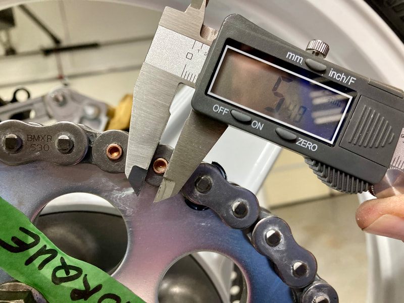
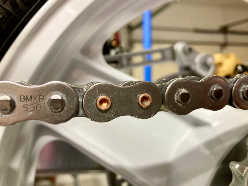
7 • Screw-type Drive Chain Master Link Install
8 • Muffler Installation Tip
9 • Fork Leg Refinishing
10 • Muffler Refurbishing - OEM
11 • Muffler Refurbishing - Yoshimura
12 • Decal Removal (No Mar)
13 • Small Coolant Hose Generic Replacement
14 • Reshaping A Chain Guard
15 • Steering Head Bearing Replacement
16 • Refurbishing Paintwork
17 • Carburetor Removal
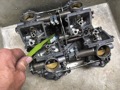
18 • Carburetor Disassembly & Cleaning
19 • Preparing For Carb Sync
20 • Carburetor Installation
21 • Carburetor Synchronising
22 • Chain Slider Fix ('86-87)
23 • Brake Caliper Disassembly
24 • Mirror Refurbishing
25 • Gas Siphoning Made Easy
26 • Plugging the PAIR Ports
27 • Eliminating The Stator Wiring Connector
28 • Charging System Check & Diagnostics
29 • Windscreen Refurbishing & Plastics Care
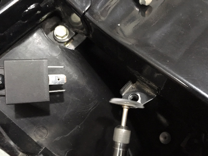
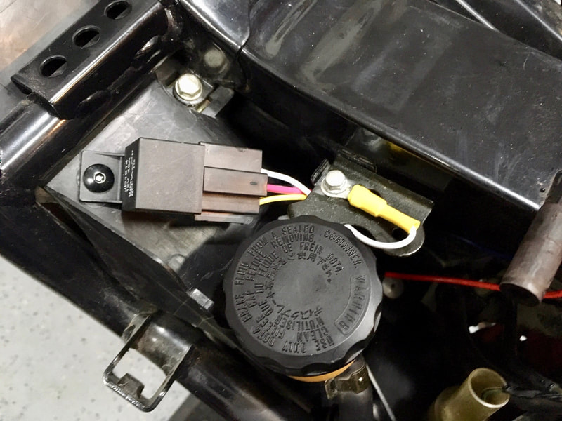
30 • Electrical Relay Installation
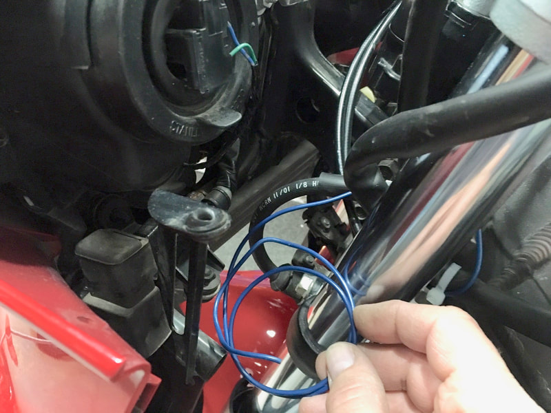
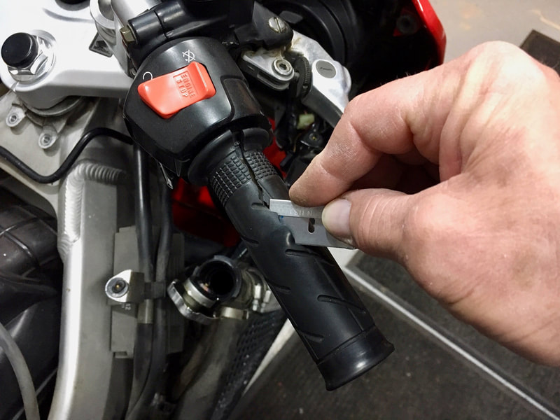
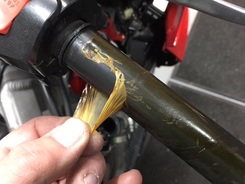
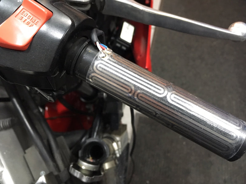
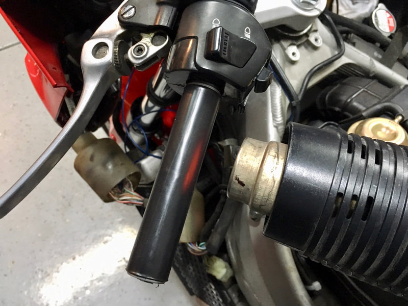
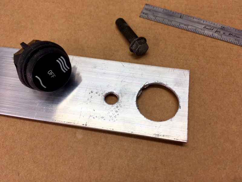
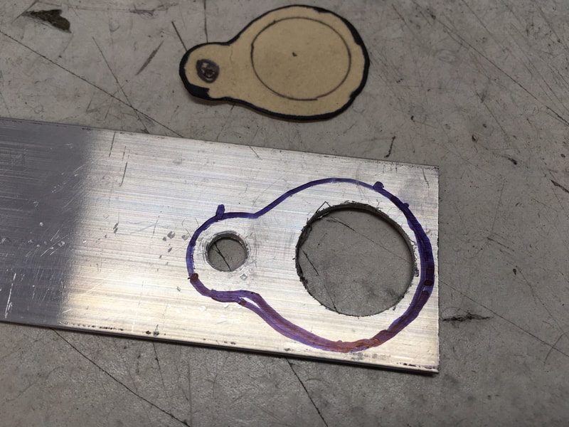
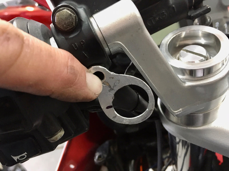
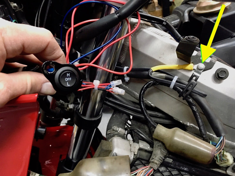
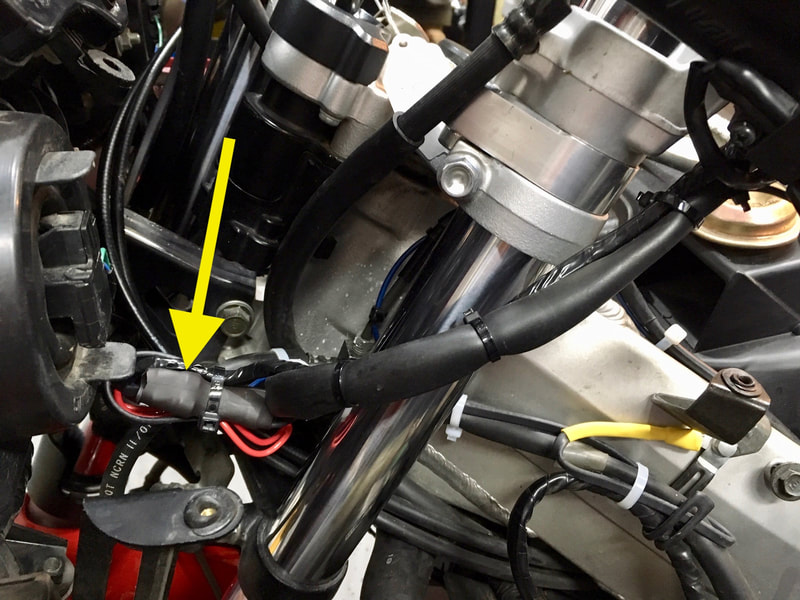
31 • Heated Grips Installation
32 • Priming Carbs, Testing A Fuel Pump, Empty A Fuel Tank
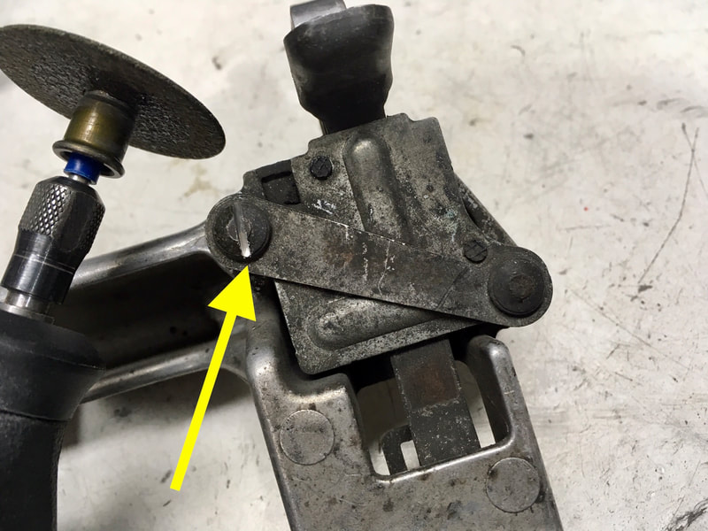
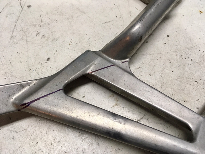
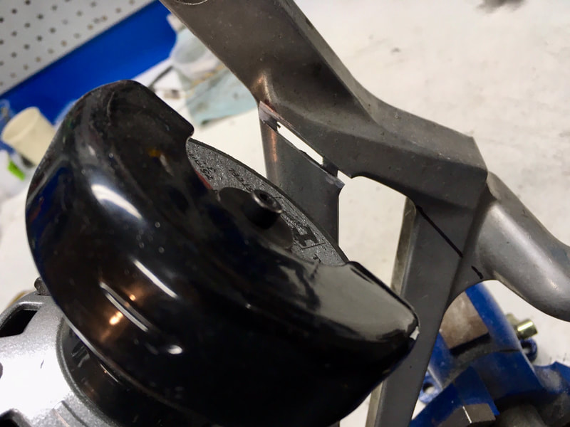
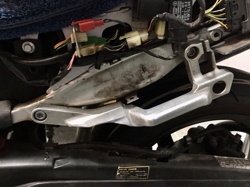
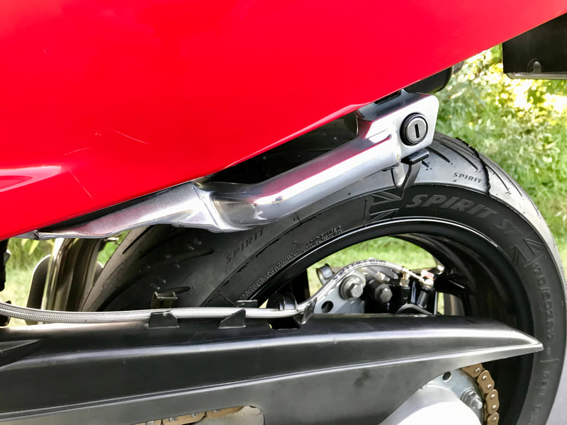
33 • Trimming or Eliminating Passenger Peg Brackets
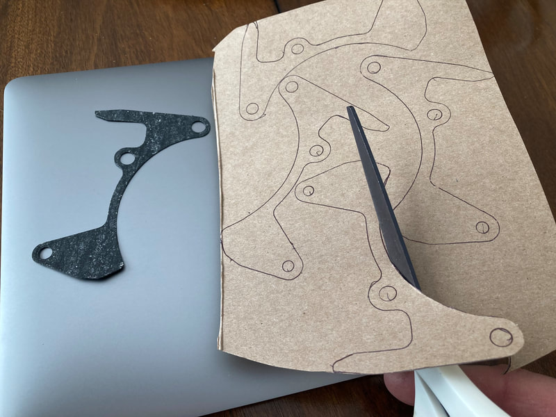
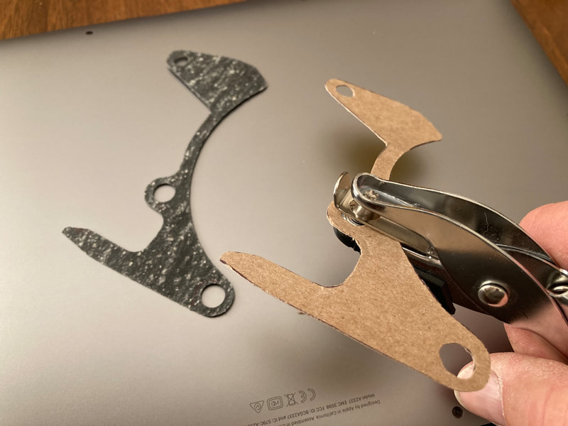
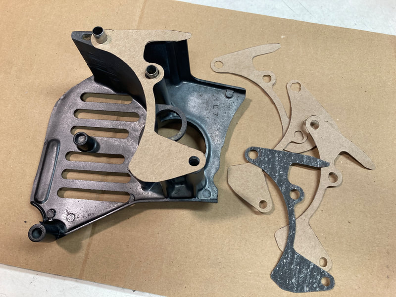
34 • DIY Gaskets
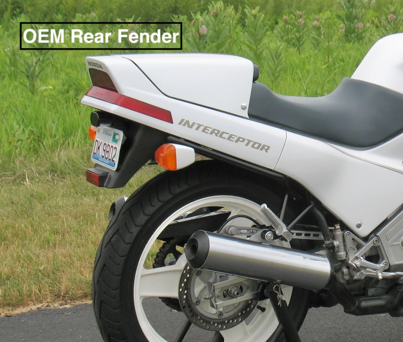
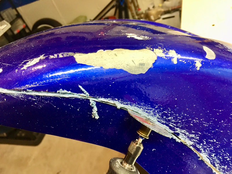
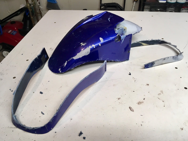
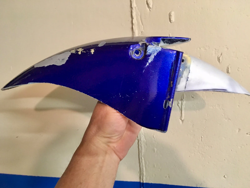
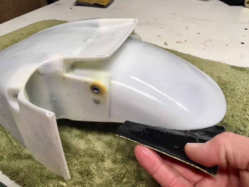
35 • Modify Fenders, Front & Rear — 2d-Gen
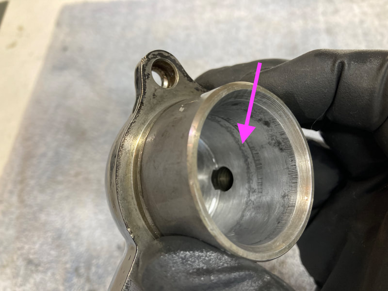
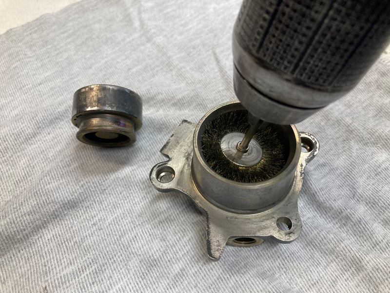
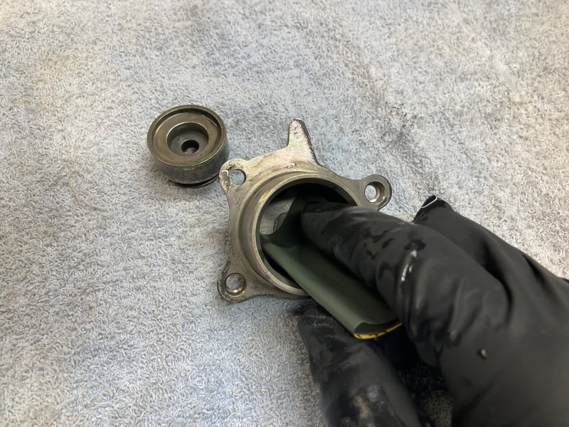
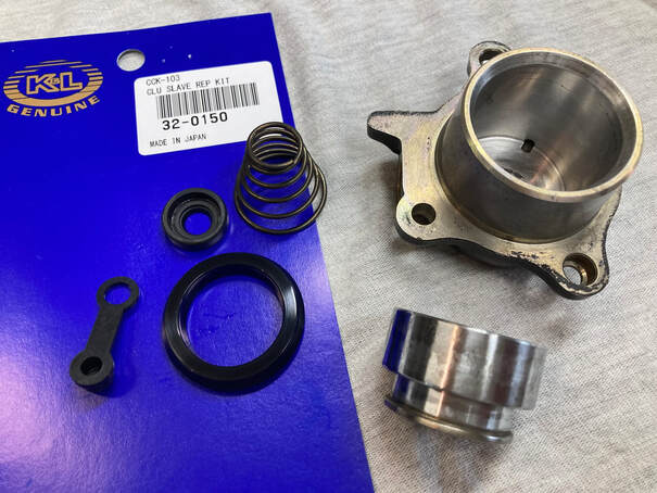
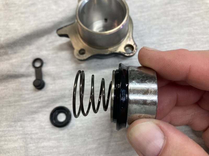
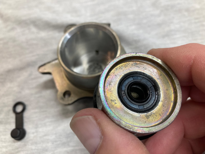
36 • Clutch Slave Cylinder Overhaul
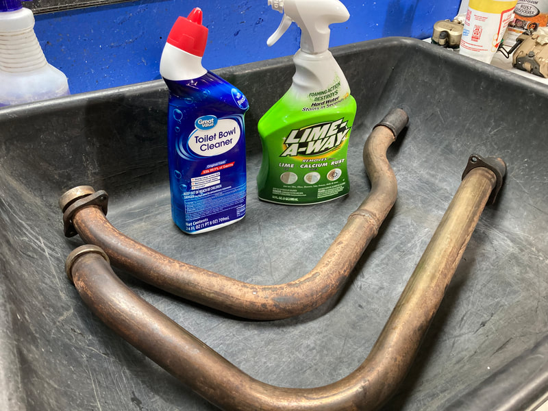
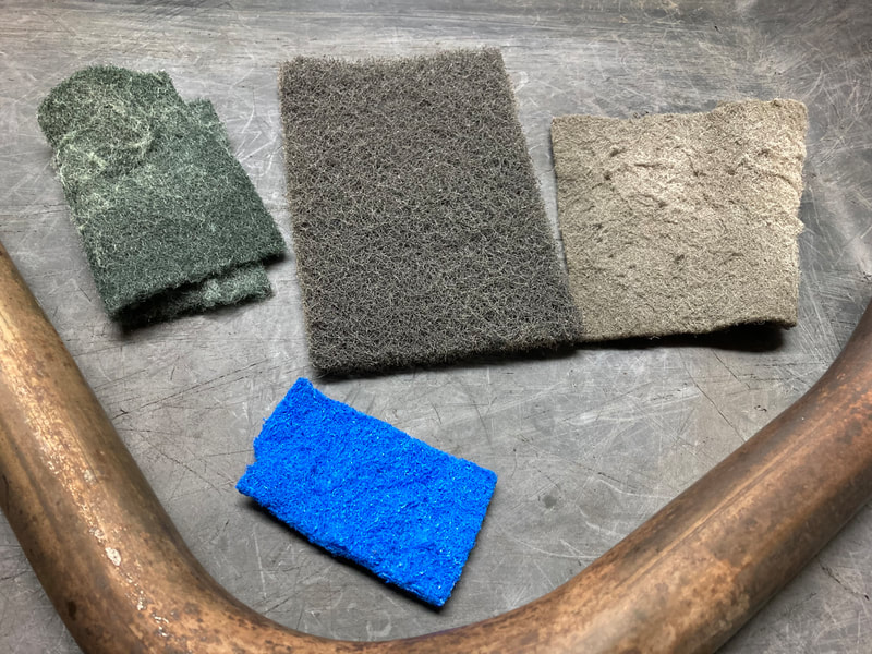
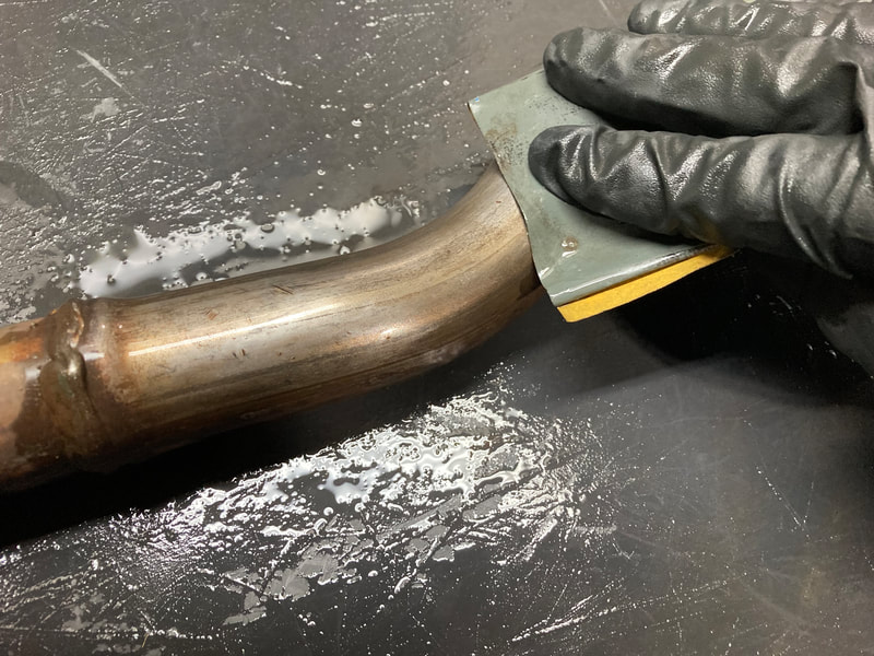
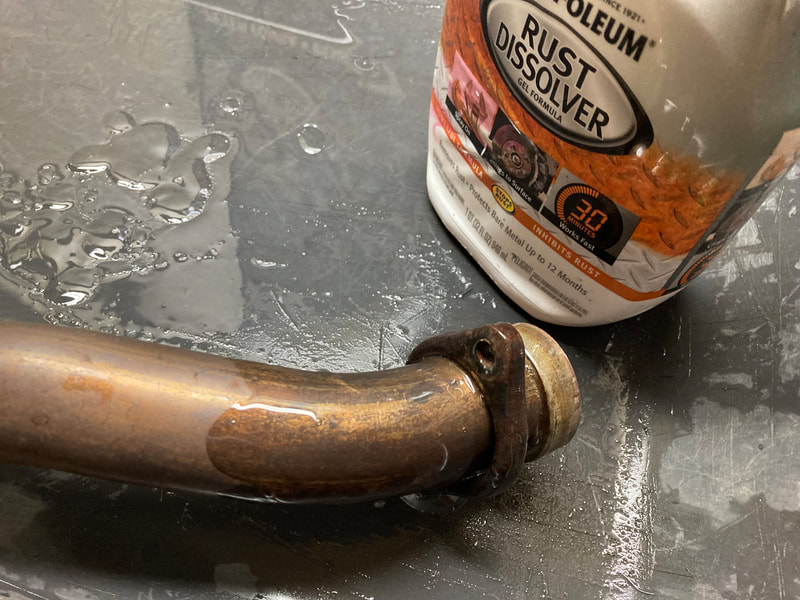
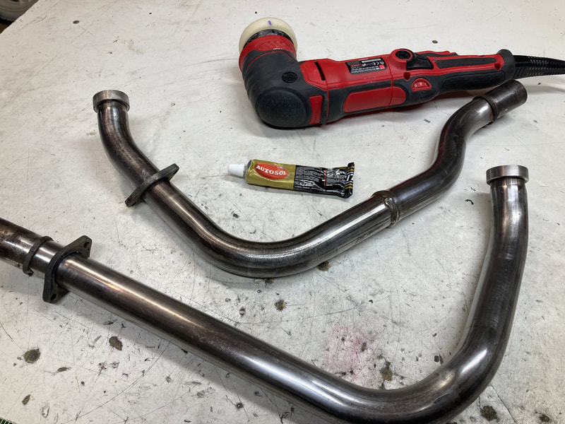
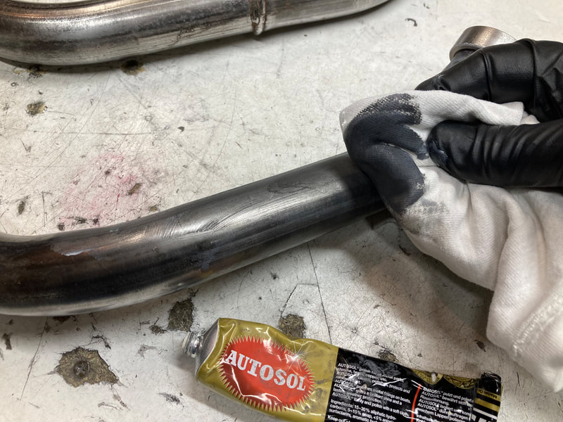
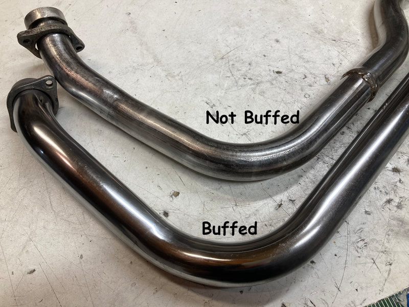
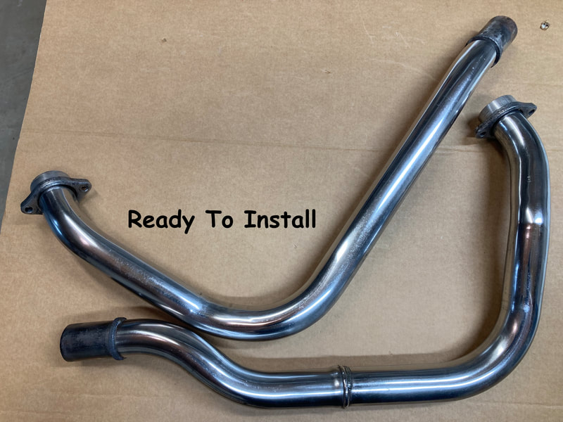
37 • Refurbishing Exhaust Pipes
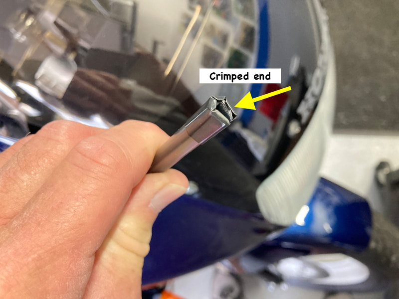
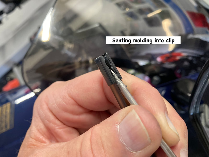
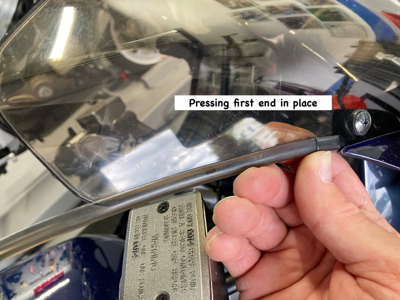
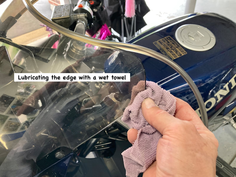
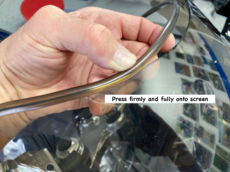
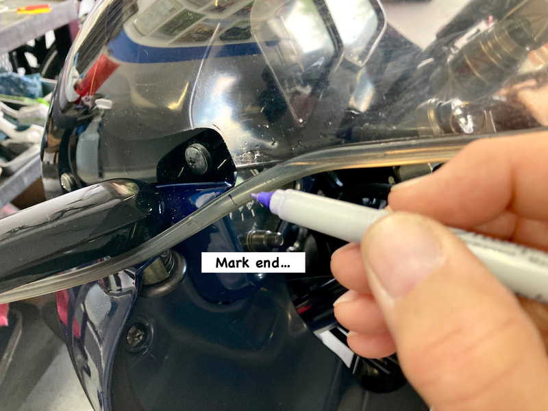
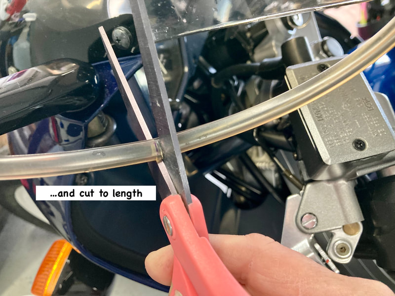
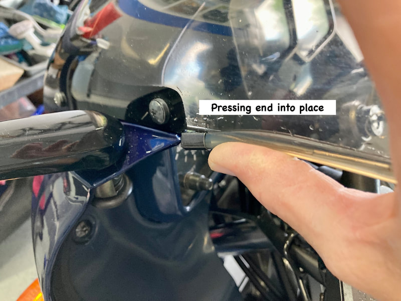
38 • Installing Windscreen Molding — 2d-Gen
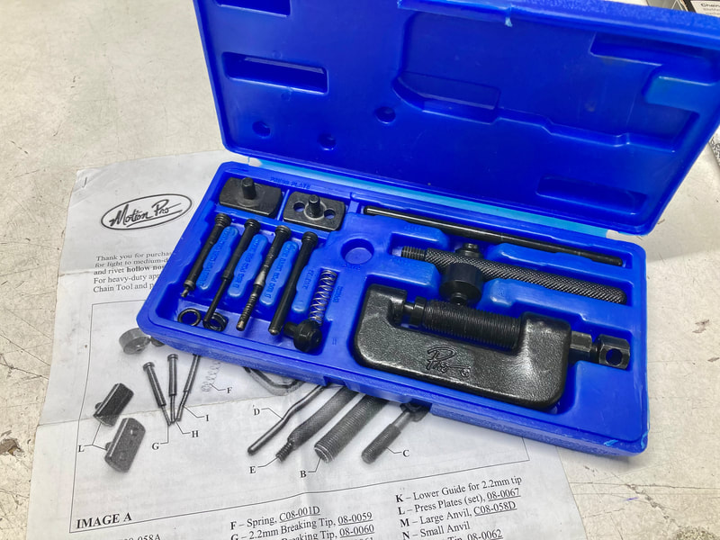
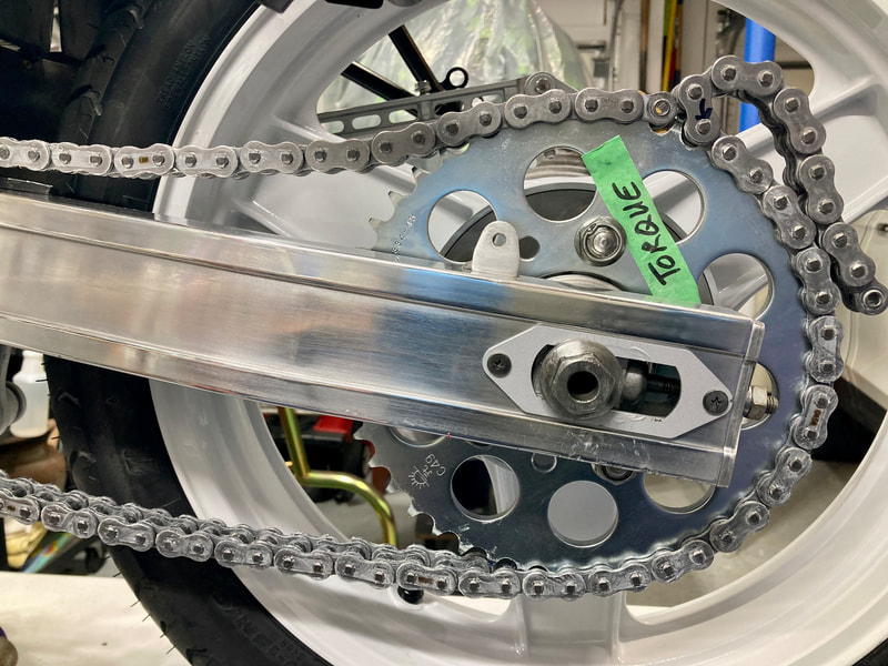
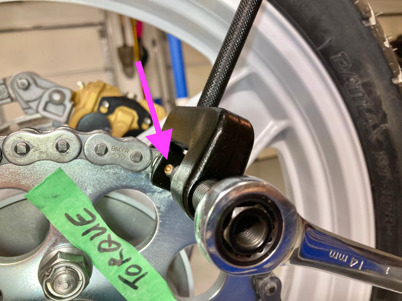
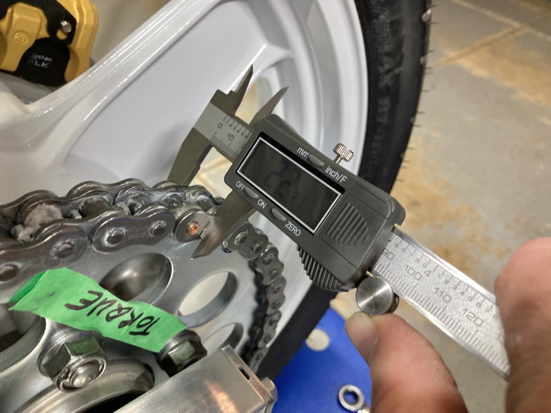
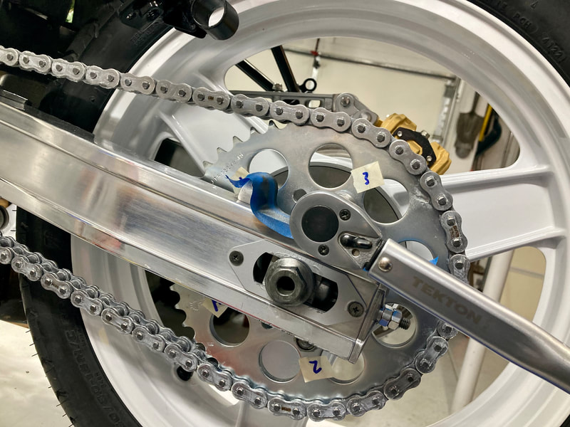
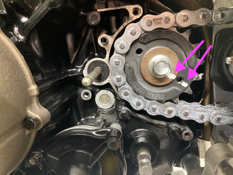
39 • Chain & Sprocket Installation
"The Shop Blog" PDF Index 2015-24
Your browser does not support viewing this document. Click here to download the document.
1. Carb Fuel Joint O-ring & Fuel Line Replacement (1986-97)
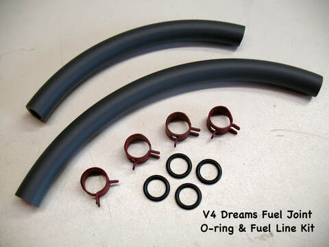
Honda calls their plastic fuel distribution tubes "fuel joint sets," but I just call them tubes. Their job is to distribute fuel from the inlet line to each carb. There's two tubes, one for carbs 1 & 3, and one for carbs 2 & 4. The point where they enter the carburetor needs to be removable for service and also have a bit of flexibility in use, so they're sealed with o-rings. Like all of our rubber fuel parts they were not designed with modern fuel chemicals in mind, like ethanol. This fact, combined with heat and age, makes them a weak point in the fuel system. I replace them as a matter of course on all my projects, along with the two flexible inlet lines. Today we have the advantage of VITON o-rings and TYGON fuel line which can stand up to anything the chemical engineers can throw our way.
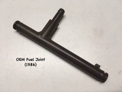
The plastic tubes with o-rings are still available from Honda for about $42 each. There's also an eBay seller who offers metal replacement tubes/o-rings for about $85 a set. On my "Products" page I offer a repair kit consisting of four o-rings, two fuel lines and clamps for $20. Whichever direction you choose, the installation is the same, and here's how I do it....
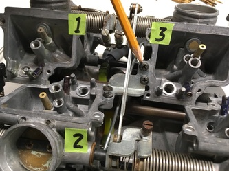
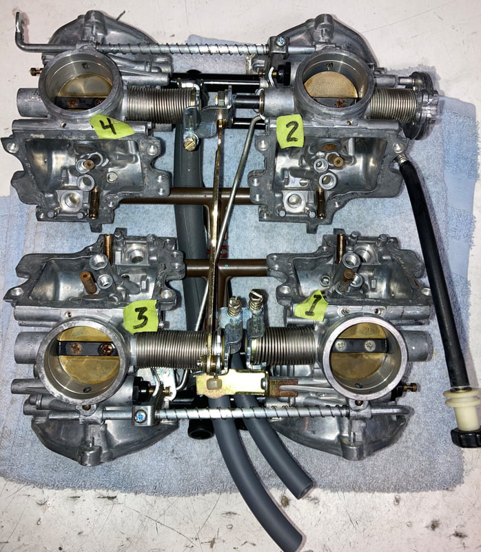
Note: the carbs are numbered as follows: Viewed from the rider's seat;
#1 is left rear
#2 is left front
#3 is right rear
#4 is right front.
Note: the carbs are numbered as follows: Viewed from the rider's seat;
#1 is left rear
#2 is left front
#3 is right rear
#4 is right front.
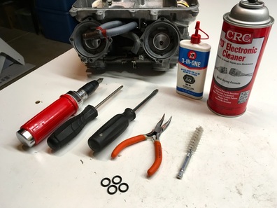
To paraphrase Hippocrates, "First, do no harm." The idea here is to separate the carbs from the plenum and one another in order to slide the tubes away, replace the o-rings, and reassemble, disturbing the carb set as little as possible. And remember that the tubes are plastic so be gentle.
Here's the basic required tools: impact driver, screwdrivers, needle nose pliers, cleaning brush, cleaning solvent (but not brake cleaner) and oil. A dental pick or tiny screwdriver is also useful for removing the old o-rings.
Here's the basic required tools: impact driver, screwdrivers, needle nose pliers, cleaning brush, cleaning solvent (but not brake cleaner) and oil. A dental pick or tiny screwdriver is also useful for removing the old o-rings.
Like everything mechanical, this process is easier with the carb rack cleaned and disassembled; see tutorial 18, "Carburetor Cleaning, Disassembly, Reassembly." I will refer to the 1986-87 model with separate references to the later models where necessary. Click on photos to enlarge.
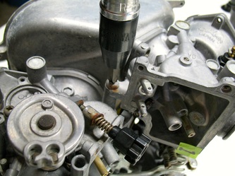
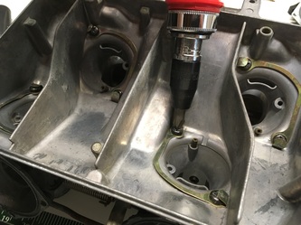
We begin by removing the plenum screws — 8 inside the plenum (16 for '94-97) plus two on the sides. Note: '90-93 do not have the two side screws, while the '94-97 have six 10mm side nuts holding long metal alignment dowels (the longer one is the center of the three). The plenum and side screws may require an impact driver to loosen (carefully). With the carb rack then turned upside down (plenum down) on the bench with carbs #2 & 4 facing me, remove the center bracket. Note: '94-97 have no center bracket. The throttle/choke linkages connecting #2 and #3 will remain in place.
('86-87 carbs shown)
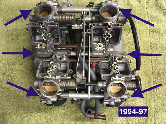
(Right) Location of the six nuts securing the carb rack; '94-97
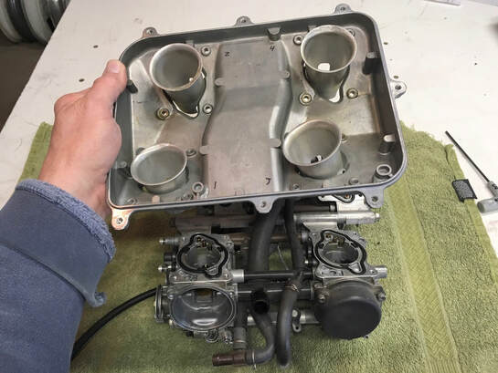
With all the screws/bolts off, the plenum can be lifted off.
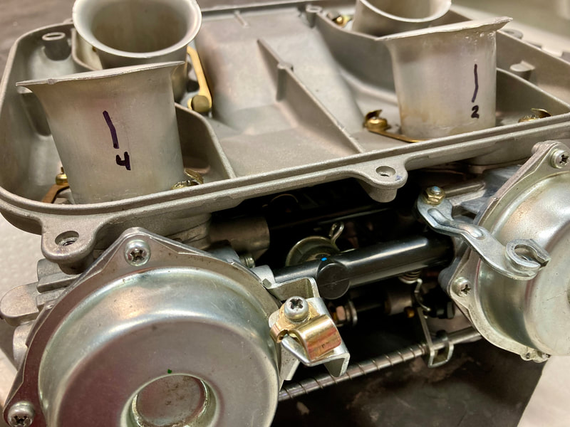
On the '90-97 (below left, 1995 pictured) first note how the four velocity tubes are located to help with reassembly. It may help to mark the tubes with a reference line to the top screw of the diaphragm cover (below right, 1993 pictured).
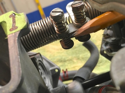
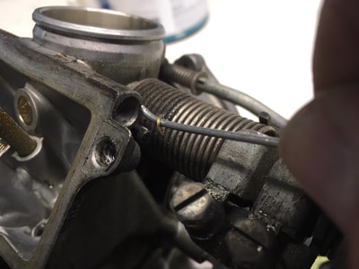
I now remove the tiny sync springs — not the screw and spring, just the springs underneath. TIP: It helps to first unscrew them 4 or 5 turns and, when reinstalling the spring during reassembly, screw the same amount back in — this is important, as it helps retain what "sync" the carbs began with. The #3 sync spring needn't be removed ('86-93); same with the #2 for '94-97.
Note: 1986-93 has no adjustment screw on #2 carb, while '94-97 has no adjustment screw on #1 carb. These are the "base" carbs for syncing purposes.
Note: 1986-93 has no adjustment screw on #2 carb, while '94-97 has no adjustment screw on #1 carb. These are the "base" carbs for syncing purposes.
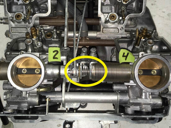
Also remove the two large throttle shaft springs — the light ones between the sync screws, not the long heavy springs.
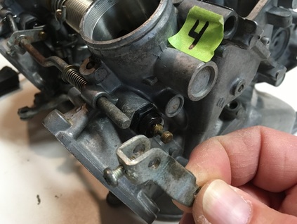
Finally, remove the choke shaft bracket at #4 by loosening its set screw and sliding the bracket off the shaft ('86-87 shown). Also loosen the same bracket at #2, visible in the upper left corner of this photo. This will allow the choke shaft to slide free as we separate the carbs.
On '90-93 loosen the brackets and slide the rod free to the right. The spring and bracket will fall free.
For '94-97, see below.
On '90-93 loosen the brackets and slide the rod free to the right. The spring and bracket will fall free.
For '94-97, see below.
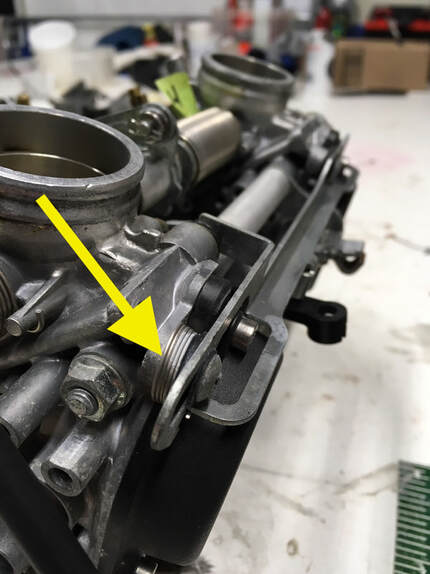
(Right) The two sliding choke rods on the '94-97 carbs are secured by two screws on each rod. Note carefully the arrangement of these screws, their washers and the spring (arrow). The choke will not operate smoothly if these are not positioned correctly upon reassembly. Also note how the choke mechanism is slotted into the long bar in order to slide it side-to-side — important for correct reassembly.
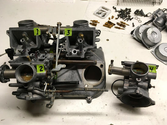
I wriggle completely free all four carbs ('86-87 pictured). Note that the carb bases are located to the plenum on dowel pins with large sealing o-rings.
Now is the time to note how the lines are routed, you may want to take photos. I then cut the old hardened fuel lines (assuming they’re being replaced) as short as possible to get them out of the way (don't pull on them, you could break the plastic tubes) and gently free the #2/4 fuel tube and then the #1/3 tube from the carb bodies.
Now is the time to note how the lines are routed, you may want to take photos. I then cut the old hardened fuel lines (assuming they’re being replaced) as short as possible to get them out of the way (don't pull on them, you could break the plastic tubes) and gently free the #2/4 fuel tube and then the #1/3 tube from the carb bodies.
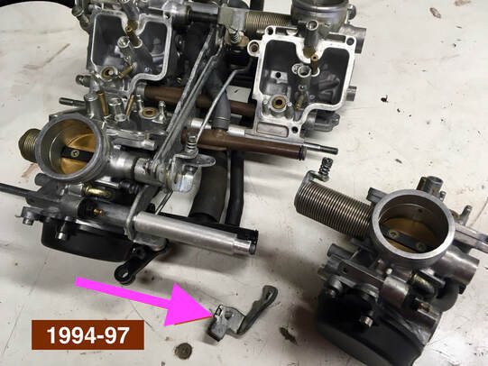
(Right) On the '94-97 note the small bracket at the bottom of photo. Note exactly how this bracket was located, you won't want to forget it during reassembly.
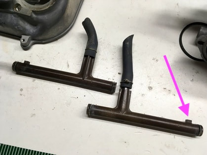
The tubes are identical — just installed in a mirrored fashion ('86-93). There may be fitting nubs on the '86-87 carbs, one per tube — one nub fits into carb #1 and one into #4 (pink arrow). Note: 1990-97 have no fitting nubs.
Those old, hardened fuel lines will make installation more difficult and really should be replaced. Now's your chance. If the fuel lines are reluctant to come off the plastic tubes, warm them with hot water.
The two black air vent tubes will have fallen free, just let them hang free till installation. Note: 1990-97 have four black vent tubes. I reuse the vent tubes' o-rings as they're not critical seals.
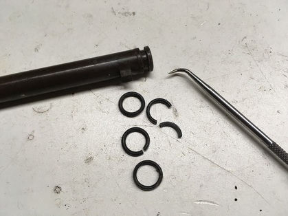
Remove the old o-rings, clean the grooves and install the new.
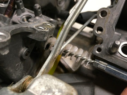
I now take a moment to clean the holes where the o-rings will seat with a bit of electronic cleaner (not brake solvent) and small brush, taking care to avoid any debris going into the carbs. If your carbs are disassembled like those in the photo, just blow air or cleaner into the threaded float valve hole visible at the upper left to flush this passage and ensure there's no gunk left behind.
We're ready to reassemble!
We're ready to reassemble!
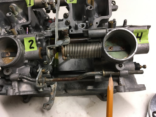
Reassembly, as they say, is the reverse of removal. Fit the fuel lines onto their respective fuel tubes — the shorter line connects to the #1/3 tube and the longer to the #2/4 tube, then thread them through the carb rack the same way they were removed (you took notes, right?). There's reference photos at the end of this post.
Fitting all the tubes and linkages back together is a bit like herding cats, but it can be done. Coat the new o-rings with a bit of oil or grease and fit #1/3 tube into place followed by #2/4, remembering that the locating nubs fit into carbs #1 & 4 ('86-87). The choke shaft will have fallen free of #1 & #4, so be sure it and its spring (the pencil is pointing to it) are back in place before mounting #1 & #4 on the plenum ('86-87) — '90-97 choke shafts can be installed later when the carbs are together. When all the fuel and vent tubes are lined up, work all the carbs back into place and fit onto their respective plenum mounting dowels ('86-93). For the '94-97 insert the three long locating dowels to hold everything in place — these should slip into place easily if everything is lined up. Don't forget the large o-rings between each carb and plenum — make sure they're back in their grooves.
None of this requires force. If you find yourself reaching for a hammer, take a breath and figure out why. It's a three dimensional puzzle, but it does fit back together.
When everything's back in place, hold the whole affair together while carefully righting the carb rack and loosely reinstall the plenum screws, side screws or bolts, and then the center bracket on the underside ('86-93) — again, they should all go in and bottom easily if everything is lined up. The velocity tubes on the 1990-97 fit under the plenum and into slots in the carb bodies — take care to line up all four tubes before snugging the screws down. Once all the screws/bolts are in place, tighten them up. Flip the rack upside down and reinstall the missing shaft and sync springs (be careful, these will try to pop out and escape across the room). On the '86-93 the larger shaft spring goes between #2/4 and the smaller between #1/3 — for '94-97 the longer goes between #2/4, the shorter between #1/3. During the reassembly process, you should be continually checking that the throttle and choke mechanisms are free and correct. There should be no binding.
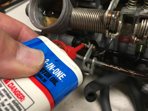
Apply a bit of oil to the pivot and sliding areas of the choke and throttle linkages. Visually check that all the carbs are seated square and flush, and that the carb-to-plenum o-rings haven't become dislodged.
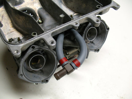
Install the fuel lines onto the "T" fitting. When installed correctly, the different length replacement fuel lines will look like this, facing carb #1 just like from the factory. If using my replacement lines, you may want to shorten one or both slightly to get the correct curvature of the fuel lines without crimping.
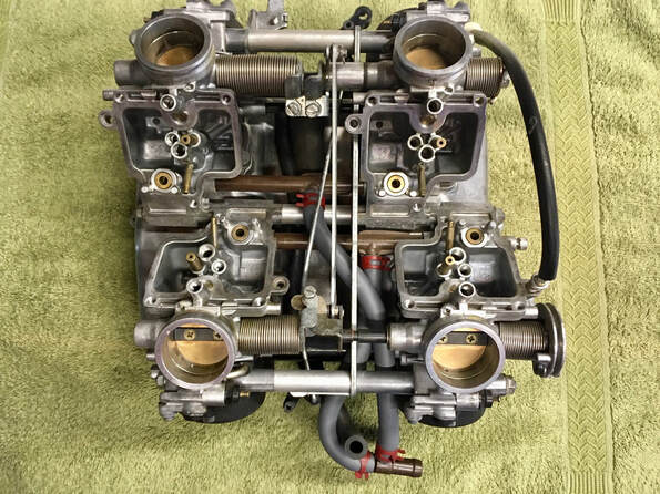
FOR REFERENCE:
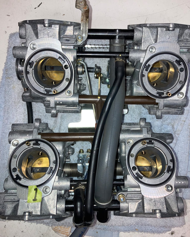
(Right) Here's a look at the '94-97 carb rack with new fuel lines installed showing the correct routing and the "T" fitting.
(Below) Here are top and bottom views of the '90-93 rack showing correct routing of the lines.
(Right) Here's a look at the '94-97 carb rack with new fuel lines installed showing the correct routing and the "T" fitting.
(Below) Here are top and bottom views of the '90-93 rack showing correct routing of the lines.
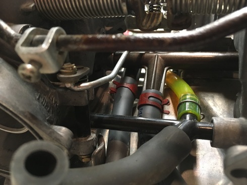
(Right) Here's a reference photo for the '86-87. On this carb set the vent line happens to be green colored so gives a good reference as to how the grey fuel lines should be routed. Here we're looking upside-down between carbs #1 & 3.
After all this fiddling about, the carbs will need to be sync'd on the running bike. Syncing is an important step on any multi-cylinder, multi-carb engine and shouldn't be ignored.
TIP: install the sync fittings onto the engine intake manifolds before installing the carbs.
TIP: Check the carb set for leaks before mounting on the engine; see tutorial #20, Carburetor Installation.
Congratulations, you're done!
Your carburetors thank you.
2. Rear Caliper Sleeve Replacement ('86-87)
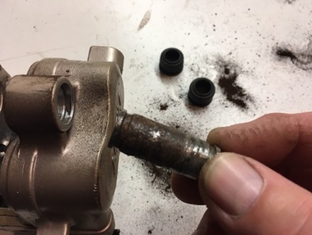
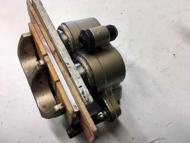
On nearly all of my projects I come across an all-to-common issue — the lower mounting point on the rear caliper of the 2d-gen model.
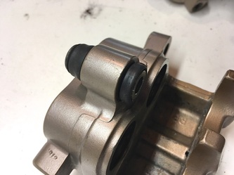
The mount consists of this "sleeve," as Honda calls it, which is required to slide slightly to & fro in its boss as the brake is cycled. Trouble is, this particular pin is usually severely corroded and often frozen in place. The brake will still function but at a fraction of its potential. It seems well-protected by two tightly-fitted rubber boots (shown in background) but still suffers from its location at the bottom of the caliper.
The mount consists of this "sleeve," as Honda calls it, which is required to slide slightly to & fro in its boss as the brake is cycled. Trouble is, this particular pin is usually severely corroded and often frozen in place. The brake will still function but at a fraction of its potential. It seems well-protected by two tightly-fitted rubber boots (shown in background) but still suffers from its location at the bottom of the caliper.
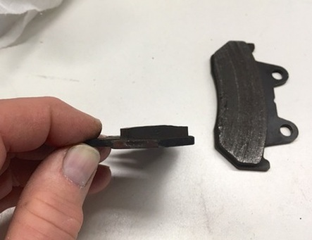
This is the result of the sleeve being frozen in place by corrosion. The inboard brake pad isn't allowed to slide freely, resulting in only the upper portion making contact with the disc. Note the bevelled profile of the inboard pad. These pads are junk.
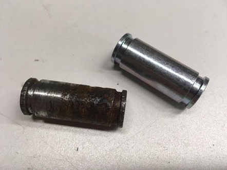
Fortunately, the sleeve and boots are still available from Honda. The sleeves retail for about $12, the boots $4.
Often, freeing the sleeve from the caliper is difficult — this one was soaked overnight in penetrating fluid and then twisted loose. I've also taken these to a machine shop where they can press them out in a few minutes, often at no charge. The boots are often in reuseable condition.
Often, freeing the sleeve from the caliper is difficult — this one was soaked overnight in penetrating fluid and then twisted loose. I've also taken these to a machine shop where they can press them out in a few minutes, often at no charge. The boots are often in reuseable condition.
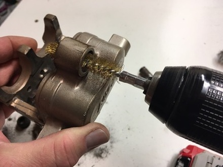
The bore itself typically only needs cleaning with a brass brush and flushing with brake cleaner. I then coat the bore with some silicone grease and reinstall the sleeve and seals — there's a trick to this; install one seal, push the sleeve all the way through from the opposite side, install the second seal then slide the sleeve back to the second seal, engaging the seals in the slider grooves.
I'm sure if these sleeves were serviced at each brake pad replacement or say, ten years, they'd remain in useable condition.
Job done!
I'm sure if these sleeves were serviced at each brake pad replacement or say, ten years, they'd remain in useable condition.
Job done!
3. Master Cylinder Rebuild
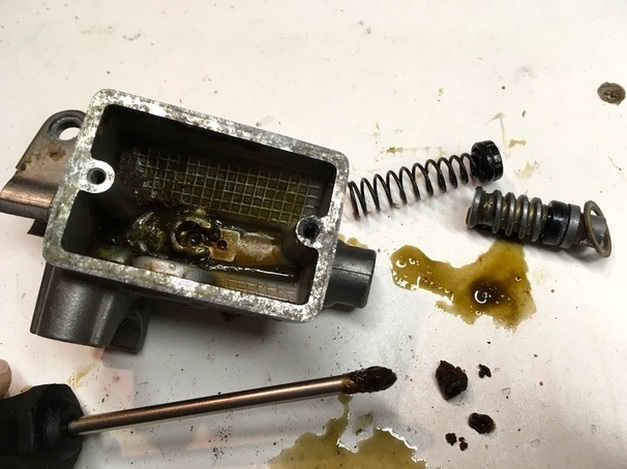
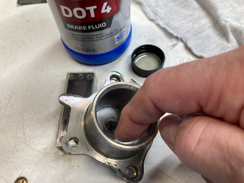
Of all the systems on a vehicle, the brakes are a high-priority maintenance item. I always remove the complete braking systems, disassemble, clean and rebuild with fresh parts. Here, I'll tackle the clutch and front brake master cylinders.
All too often when I open up the master cylinders this is what lay in wait. This situation is very common with my projects and is due to nothing more than neglect. Brake fluid should be flushed every two years, and this is the long-term result of ignoring that maintenance item.
All too often when I open up the master cylinders this is what lay in wait. This situation is very common with my projects and is due to nothing more than neglect. Brake fluid should be flushed every two years, and this is the long-term result of ignoring that maintenance item.
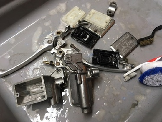
I don't know how that solidified gunk forms, but fortunately it cleans up with a straightforward sudsy washing.
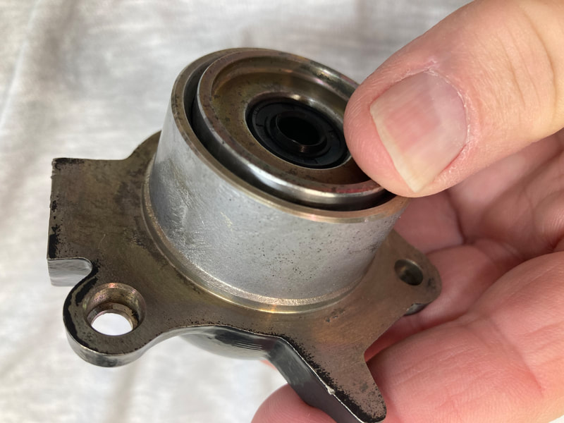
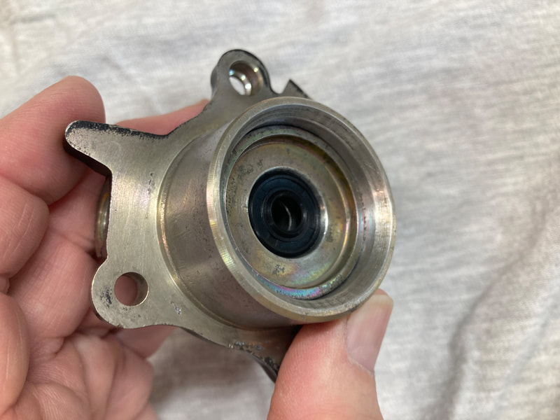
Both of these master cylinders will require a complete rebuild. That involves new seals and replacing the aged sight glasses.
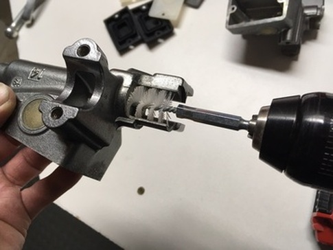
I clean the bore with solvent and a plastic rotary brush. If the bore then passes a visual inspection I move on with the sight glass repair before installing the new seals — I don't want to risk debris from the old sight glass contaminating the seals. (Sight glass replacement is covered in the next tutorial)
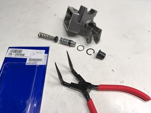
Here's the rebuild kit ready for installation. Coat the parts with Red Rubber Grease or brake fluid and carefully install into the bore in the order shown. Pictured is the clutch master from an '86-87 VFR.
I hold the assembled plunger down in the bore (against the spring pressure) with a screwdriver while inserting the circlip, verifying that the circlip is fully seated. The K&L bent-tip snap ring pliers makes this juggling act a much smoother operation.
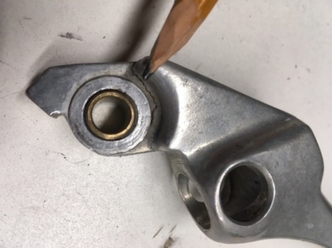
Next up are the levers. Motion Pro and probably others make complete reproduction levers for the VFR, but there's nothing like the originals if they can be saved.
A thorough inspection is called for with these old parts and their unknown history. While looking over the brake lever I discovered this crack on the underside. It obviously resulted from a crash or tip-over. No question that this one goes into the trash bin.
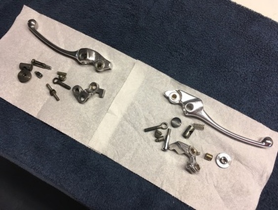
Who knew these adjustable levers have so many parts?
After a thorough cleaning, de-rusting and polishing, I carefully reassemble the levers with a touch of silicone or lithium grease on all the rotating parts. Fresh stainless steel reservoir screws are a finishing touch.
Once the sight glass lenses are installed, these reservoirs are ready for the next 30 years.
4. Sight Glass Replacement For Brake & Clutch Master Cylinders
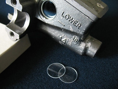
The OEM master cylinder sight glass lenses are made of some sort of plastic. After 30+ years of exposure to brake fluid and sunlight they've become cloudy, brittle and even opaque. This defeats their purpose as a sight glass to check the fluid level and in the worst case can result in leakage — brake fluid makes a very effective paint remover as it drips onto your nice fuel tank. Time to fix it.
Replacement lenses can be sourced inexpensively through eBay or Amazon. To determine the correct size lens, remove your old lens, backing plate and o-ring. Using a sliding caliper, measure the hole diameter that the lens will be sitting on. Order a lens sized to just fit into the hole but still rest on the base ridge, i.e. 16mm. I recommend lenses made of glass.
Here's my replacement process:
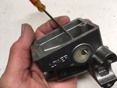
I begin with the demolition of the old plastic window. A tap with a small screwdriver from the inside starts the process. Then, using a larger flat-blade screwdriver I pry around the perimeter from the outside, working my around.
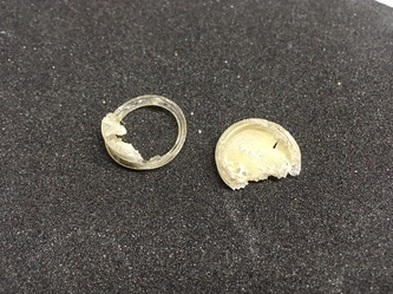
Sometimes they come out pretty cleanly, as here, and sometimes not…keep at it, they will eventually be defeated.
I also remove the metal backing plate and its o-ring.
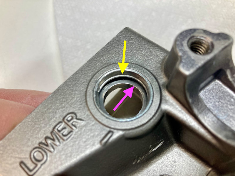
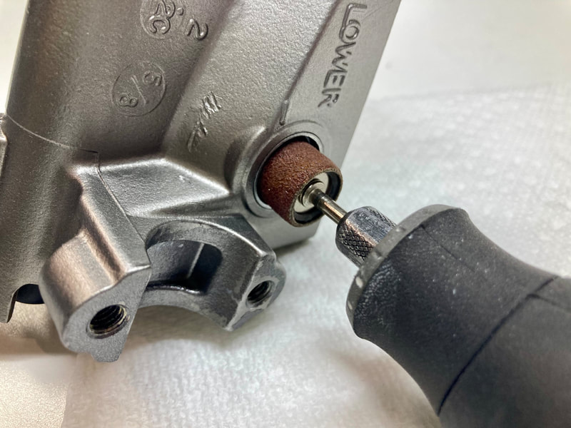
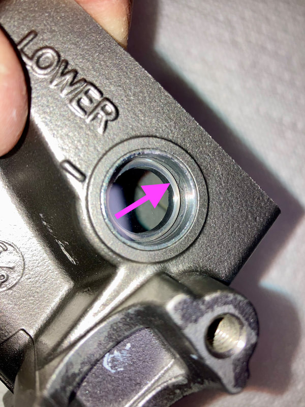
(Below) The idea is to get to the ridge at the bottom of the hole (pink arrow). In the case of this master, that ridge has a 15mm hole diameter, while the main casting hole diameter is 16mm, so that's the maximum size I'll be able to fit into the recess. However, there's a second ridge (yellow arrow) which won't allow the 16mm lens to drop into place. I gently grind that away with a sanding drum mounted on the Dremel until I can just slip the 16mm lens into place.
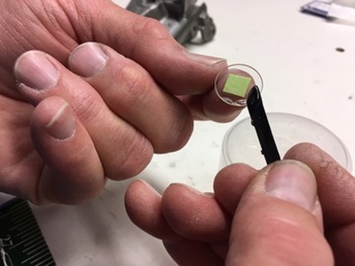
After a final cleaning of the lens and it's seating groove with acetone or similar, I fill the groove with adhesive, then stick the lens on a finger tip (using rolled-over masking tape) and carefully apply adhesive around the perimeter.
I use good ol' JB Weld, which claims to be impervious to most chemicals. It also drys to a dark gray, which works well here.
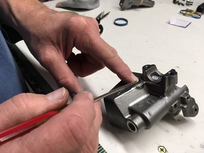
Carefully set the lens in place to fully seat it in the adhesive but not so hard as to squeeze the adhesive too thinly.

I allow the adhesive to fully cure for a day or two. Expect some residual adhesive to show, but overall a practical repair.
Job done!
5. Carburetor Bowl Gasket Replacement
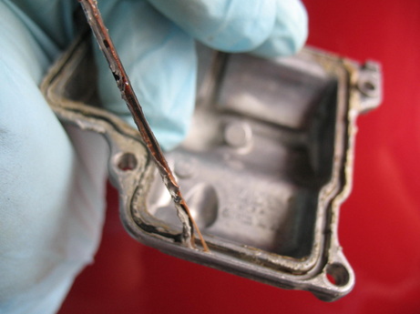
The combination of time and modern fuels have conspired to make the replacement of the OEM carburetor float bowl gaskets an eventual necessity. This operation is straightforward but does require the removal of the carb rack (see tutorial #17, Carburetor Removal), so plan a full afternoon in the garage. In this tutorial I'm picturing the '86-87 carbs.
The good news is that we now have accessibility to modern, inexpensive replacement gaskets in the form of VITON o-rings. These o-rings are superior to the OEM gaskets, especially in their care-free attitude toward ethanol. They're available on the "Products" page or my eBay listing.
If your carbs are leaking after storage this is a likely culprit (along with the fuel tube o-rings). I sometimes find this mess with my projects (right), where a desperate previous owner has gooped some sort of sealer on the gasket to try to seal it — please don't do this.
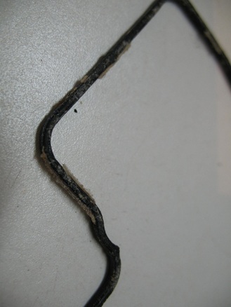
The dried and brittle old gasket will likely look like this.
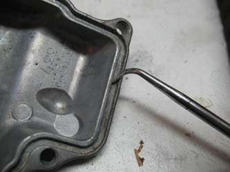
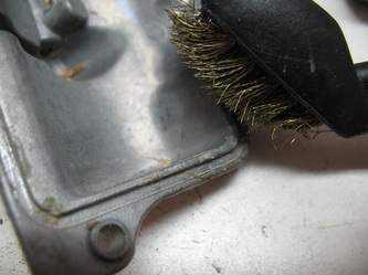
Both the gasket groove in the bowl and the sealing surface on the carb body will need to be cleaned. I use a tiny screwdriver blade or dental pick to scrape out most of the hardened residual cement from the bowl groove. Then a brass brushing followed by a wash and rinse.
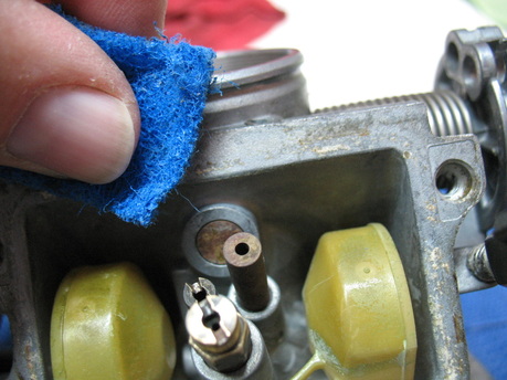
Next I tackle the carb surface. Using a kitchen scrub pad, I clean the sealing surface of any residual contaminates, being mindful of getting dirt into the carb bowl. I then gently blow out the bowl area with compressed air or by blowing through a soda straw. The floats are easily removable if you want more accessibility to the bowl.
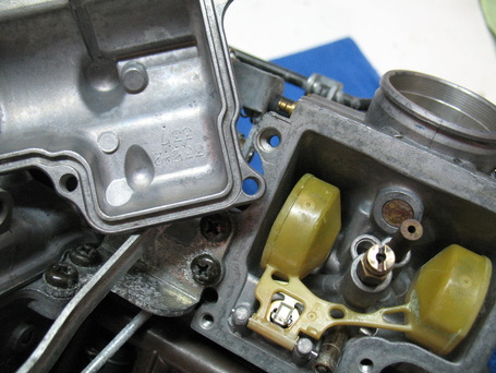
You want the sealing surfaces to look like this.
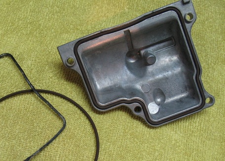
The o-ring gaskets are simply pressed into place and the bowl screwed back onto the carb (don't overtighten the screws). If the gaskets are reluctant to stay in place (especially true with the '94-97 carbs) a bit of grease or small dabs of gasket cement will help hold them in place during installation. Avoid the temptation to use RTV or gasket sealer — it just makes a mess and can find its way into the carbs, causing future problems.
TIP: While your bowl covers are off, check the float height adjustments ('86-93).
A short video is provided below…..
TIP: While your bowl covers are off, check the float height adjustments ('86-93).
A short video is provided below…..
6. Fuel Tank Sealing
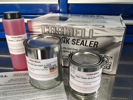
My trials and tribulations with VFR projects have included lots of fuel tanks in varying states of...ahh...despair. They're all the same relative age, so their condition is a reflection of how they've been cared for over the decades. I've come across tanks which look great on the ouside but heavily rusted internally, and just the opposite. But, like a Realtor likes to say about waterfront property, "they ain't makin' any more," so these tanks are worth saving, and that's where tank sealant comes in.
My choice for do-it-yourself tank sealant is Caswell"s motorcycle sealing kit. This kit runs $40 for clear and $55 for colored. Both are a 2-part epoxy with some pretty fancy chemists' terms associated with it (i.e. "phenol novolac is more thixotropic") but the bottom line is that Caswell claims it sticks better, even to uneven rusty surfaces and is resistant to anything short of a nuclear detonation. It will bridge and seal up actual gaps and is pretty easy to work with. Pictured above is another product I like to use on tanks with a salvageable exterior finish; Seal Mask. This pink liquid brushes on the painted finish and protects during the cleaning and application process. Pretty amazing stuff, 'cause it washes off with only clear water when finished. Caswell provides written instructions with the kit and on their website.
My choice for do-it-yourself tank sealant is Caswell"s motorcycle sealing kit. This kit runs $40 for clear and $55 for colored. Both are a 2-part epoxy with some pretty fancy chemists' terms associated with it (i.e. "phenol novolac is more thixotropic") but the bottom line is that Caswell claims it sticks better, even to uneven rusty surfaces and is resistant to anything short of a nuclear detonation. It will bridge and seal up actual gaps and is pretty easy to work with. Pictured above is another product I like to use on tanks with a salvageable exterior finish; Seal Mask. This pink liquid brushes on the painted finish and protects during the cleaning and application process. Pretty amazing stuff, 'cause it washes off with only clear water when finished. Caswell provides written instructions with the kit and on their website.
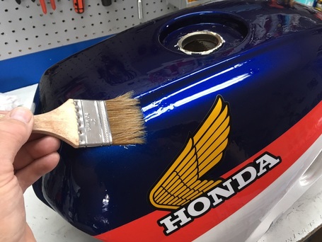
If the paint is to be saved, I first brush on one or two coats of Seal Mask, which dries in about 30 minutes to a thick plastic film. Caswell also suggests taping plastic and aluminum foil over the tank, but I've not found that necessary if you're careful. Or, use that approach in lieu of Seal Mask.
Our first task is to prep the inside of the tank as best we can. Remove the petcock; you'll need to "back blow" compressed air through the openings after sealing. I install the lower fuel level sensor with its rubber gasket and tape the top filler hole or just close the filler if it's still in place. Using acetone, I slosh about a pint of it around the interior with a double handful of small drywall screws, drain out the bottom hole, and repeat as needed.
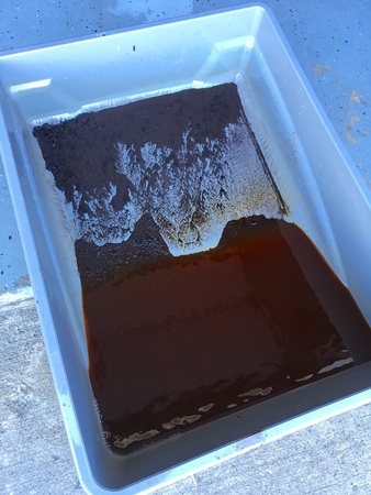
This photos shows what typically comes out of a rusty tank. The putrid smell of rancid gas can permeate a garage for a few days — be warned. When I'm happy with the cleaning operation I open up both holes and allow the tank to completely dry for a couple of days.
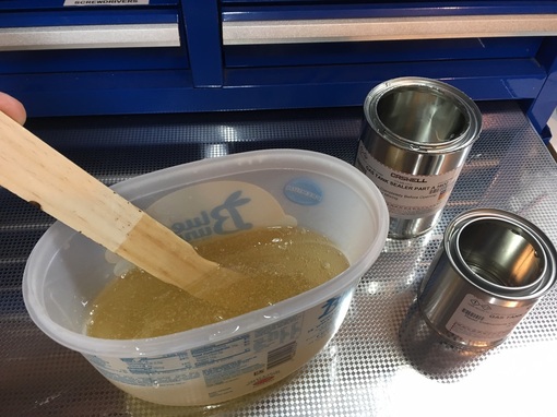
Next we need to mix the 2-part epoxy in a plastic container. Working time is dependent on air temperature, but basically be ready to pour into the tank immediately after mixing.
Shown here is the clear sealant.
Pour the very thick mixture into the filler opening (with the bottom opening taped over), tape the filler opening, and slowly rotate the tank to distribute on all surfaces. When I'm satisfied that everything's coated, uncover the lower hole and prop the tank level, a few inches off the table surface, allowing it to drain for a couple of hours. I place a plastic grocery bag or some wax paper under the the opening to allow the drained glob to solidify on it. Immediately after beginning the drain operation blow compressed air into the fuel pickup tubes (at the petcock) to clear potentially clogged pickup screens inside the tank — don't skip this step. After about an hour, I'll take a sharp blade and cut off any drips around the drain hole. Caswell suggests allowing the tank to sit a few days, undisturbed, to cure the epoxy.
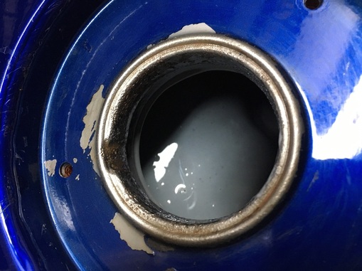
Here's a look at a cured tank interior, in grey.
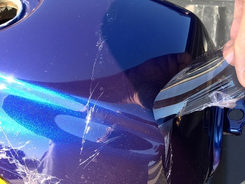
After curing, peel away the Seal Mask, or just dissolve with water.
Reassemble your refurbished fuel tank and add gas.
Job done!
7. Screw-type Master Link Install
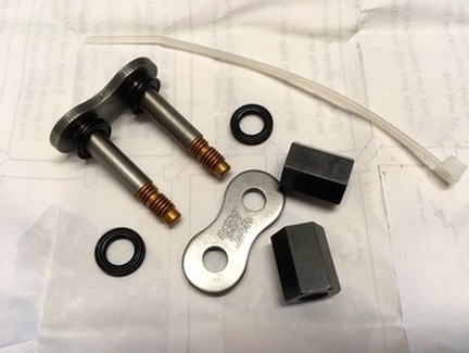
These high-performance bikes' drive chains don't, or shouldn't, use a clip-type master link, but instead require a riveted master. Assembling a master link requires the right touch when pressing (riveting) the master pins — not too much, not too little.
Here's a different approach on a master link install from manufacturer EK.
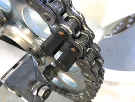
They call this a screw-type connecting link, and the objective is to take the guess work out of your master link installation. After assembling the plates, these two nuts are alternately screwed down till they bottom, which gives the correct "squish." They're then backed off to the narrowed portion of the shaft and......
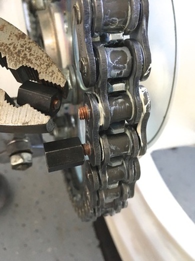
.....snapped off with a pliers. I grind down the nubs a bit for aesthetics.
This is a easy and sure-fire alternative to riveting master links. Especially handy if you only do this occasionally and don't have access to a chain breaking/riveting tool.
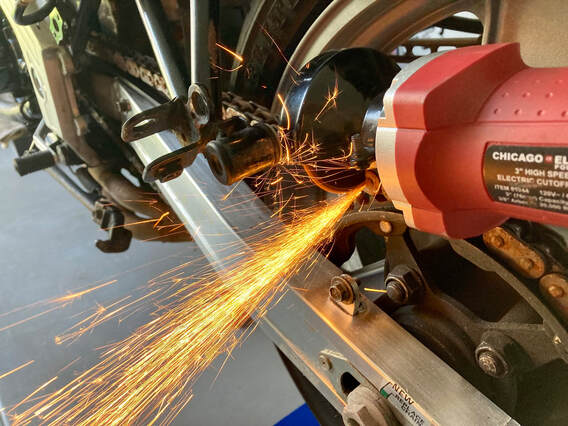
Tip: If you don't have a chain breaker, the chain can simply by cut through with a cut-off tool or hacksaw, assuming you're not reusing that chain.
A pin can also be removed by grinding down one of the pin faces and, using a hammer and drift, push the rivet pin out the backside of the plate.
A pin can also be removed by grinding down one of the pin faces and, using a hammer and drift, push the rivet pin out the backside of the plate.
8. Reinstalling Mufflers — Tip
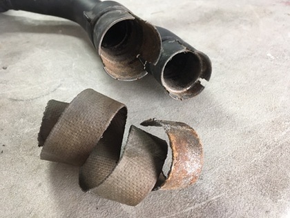
While preparing an OEM muffler set for installation on Project 18 I devised a way to make my life just a little easier. These old systems can be a real bear to remove, and even harder to reinstall. Something that would really help is to expand the female joint before sliding onto the header pipes.
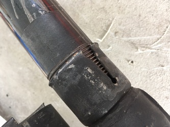
Here's one of the pipes in question, and what happened to the old exhaust gasket when removing it.
Here's one of the pipes in question, and what happened to the old exhaust gasket when removing it.
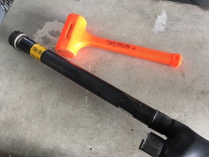
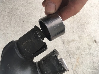
This is my homemade tool, which is the same black gas pipe I use to drive steering head bearings into place. The cut threads on these pipes are slightly tapered, so tapping the pipe into the muffler opening gently expands the opening.
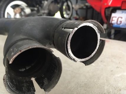
Here's a fresh gasket in place in the expanded opening. When installing the mufflers, I slip the new gaskets onto the exhaust pipes and slide the mufflers in place. Even with the expanded openings this can be a pushing and shoving match. It's never an easy chore.
The clamps are right & left specific, so be sure to get them oriented correctly before installing the mufflers.
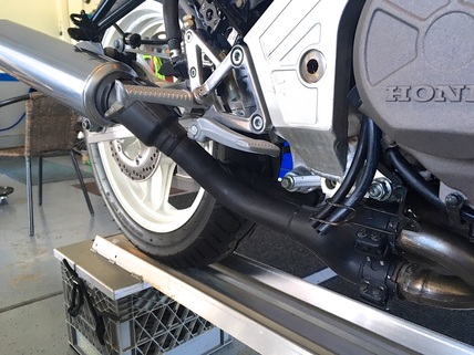
With everything test fitted, the system can be removed, the black muffler pipes sanded and painted, and they'll slip into place with much less muscle.
Job done!
9. Fork Leg Refinishing
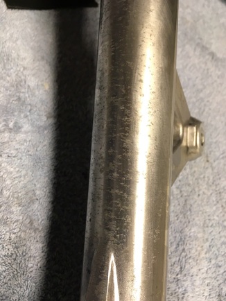
The lower fork legs on our old bikes are made of aluminum alloy. To preserve their showroom shine the factory applied clearcoat, but decades of stone chips and neglect have them looking like a bad case of acne. After a thorough cleaning I set to refinishing these aluminum lower fork legs.
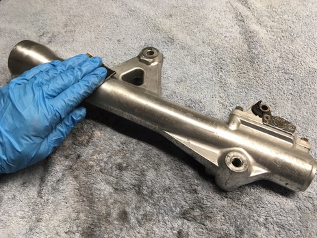
My solution is to first strip the clear-coat with chemical stripper followed by a wet-sanding with 320-grit, then 800-grit. The 320 will remove the pockmarks of corrosion and the 800 eliminates sanding marks.
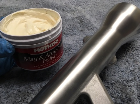
For some parts I'll go with even finer sanding, up to 3000, but I liked the dull sheen that the 800-grit provided on these legs — very factory-like. Here's the sanded part ready for polish.
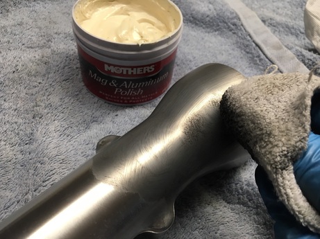
It's easy to get carried away with aluminum polishing but in this case I wanted just a bit of shine, so a single pass with Mother's Mag & Aluminum Polish did the trick.
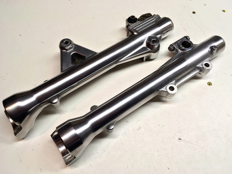
To try and preserve the finish we could have these parts powder coated with clearcoat, but I've chosen to leave them bare and remember to give them a hand polishing once a year. They live in a harsh environment where stone chipping is a fact of life, but they're very easy to access for a quick cleaning/polishing.
Job done!
10. Muffler Refurbishing - OEM
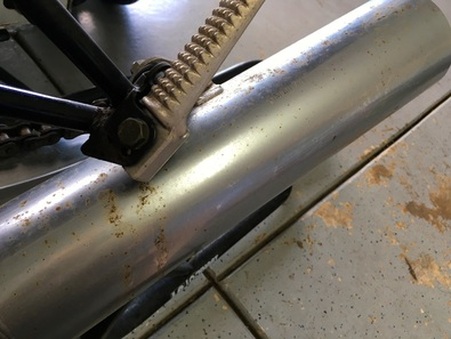
To my eye, the OEM mufflers fitted to the U.S.-spec '86-87 VFRs are made of steel with some sort of thin coating applied to the exterior (anodizing?), similar to ceramic coating but resembling stainless steel.
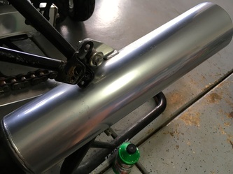
In any case, if left to the elements, the mufflers will oxidize (rust) and this is how it begins. Fortunately, if caught in time, the pipe can be saved.
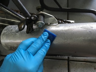
Below, I'm applying Turtle Wax Chrome Polish & Rust Remover with a non-scratch kitchen scrub pad. It pays to be gentle here and let the polish do its magic, which is to help remove the surface rust spots. I apply plenty, keep it wet, and just kind of massage it around the piece for about ten minutes.
Let it dry to a haze and buff out with a soft cloth. The deeper corrosion spots will still leave a shadow, but overall the metal is now very presentable. Repeat once per year to prevent further damage.
11. Muffler Refurbishing - Yoshimura
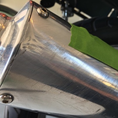
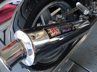
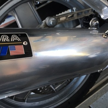
Mufflers make for effective crash bars when a spill occurs. Even an otherwise harmless tip-over will usually leave a mark on our exposed mufflers. Aftermarket cans, like this Yoshimura mounted on an '87 VFR700 F2, are often made of soft aluminum — this is good and bad: The metal damages easily but can often be repaired with some gentle persuading.
Here's a look at some rash suffered along the entire length of the muffler during a 30-mph slide. The metal is gouged and scraped. I won't be able to bring back depressed or dented areas, but I can help the other damage. The green tape is covering the Yoshimura badge to protect it during the next steps.
Here's a look at some rash suffered along the entire length of the muffler during a 30-mph slide. The metal is gouged and scraped. I won't be able to bring back depressed or dented areas, but I can help the other damage. The green tape is covering the Yoshimura badge to protect it during the next steps.
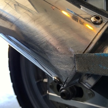
I begin with a heavy rasp to knock down the deep gouges. The blue on the file is chalk — rubbing chalk on the file keeps the aluminum filings from clogging the file. I'll follow with a finer file.
Switching to wet/dry sandpaper, I begin with 100-grit on the filed sections, and 400-grit on the scratches, then move progressively finer.
I'll end with 5000-grit which makes the final polishing a breeze.
Here, the final sanding shows a smooth but cloudy finish.
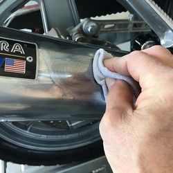
Aluminum polish applied by hand is all that's necessary to bring out the shine. The entire process took about an hour. Good thing aluminum is so forgiving.
12. Decal Removal (No Mar)
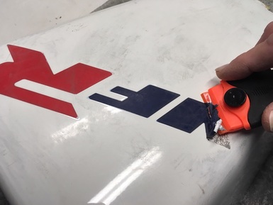
As our bikes mature with the passing years, I'm finding — more often than I'd like — that I'm forced to repaint the bodywork on my projects. The first step for any paint job is to thoroughly clean the panels followed by removing the old decals. Decal stripping be accomplished with machine sanding but that's gonna' leave a mark on the plastic parts, so I choose finesse over brute force.
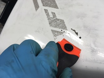
I first determine if the decal has been clearcoated. If so, I go around the edge of the decal with a palm sander to provide a clean edge. After a gentle application from the heat gun on low setting, I begin scraping with a fresh plastic razor blade. Unlike a steel razor, the plastic blade won't gouge the plastic. I can only progress about one to two inches before needing more heat — we just need the decal warmed so proceed carefully, the ABS can deform with too much heat.
I first determine if the decal has been clearcoated. If so, I go around the edge of the decal with a palm sander to provide a clean edge. After a gentle application from the heat gun on low setting, I begin scraping with a fresh plastic razor blade. Unlike a steel razor, the plastic blade won't gouge the plastic. I can only progress about one to two inches before needing more heat — we just need the decal warmed so proceed carefully, the ABS can deform with too much heat.
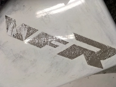
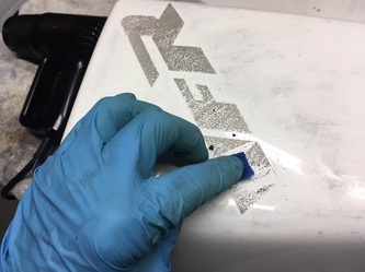
Sometimes the adhesive will remove almost completely, but more likely most will be left behind, as pictured here.
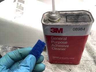
Not a problem. Using a strip of non-scuff kitchen pad, I soak a section of adhesive with 3M General Purpose Adhesive Cleaner for about 30 seconds and gently scrape the residue with a fresh plastic blade (I buy them in packs of 100). Repeat as necessary and finish with a final wipe with a clean paper towel wetted with adhesive cleaner.
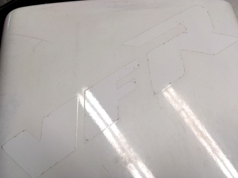
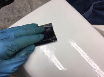
We're left with a nice clean surface, but with a distinct outline where the clearcoat edge was. This needs to be removed or it will show under the new paint.
So, my final step is a general sanding of the entire piece in preparation for paint (below, left). For this I use wet-dry 320-grit paper with a little extra attention to the decal outline.
This cowl took about 30 minutes to this point and I'll spend four or five hours removing all the bike's decals. From here I'll deal with any plastic repair and/or bodywork required.
13. Coolant Hose Generic Replacement
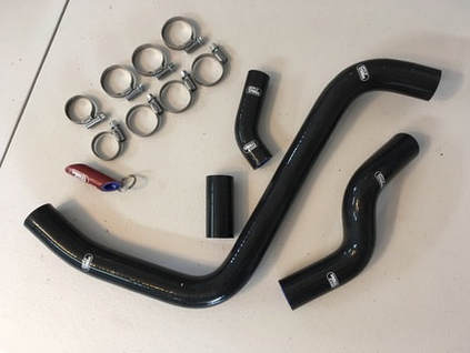
The coolant hoses for the second- through fourth-generation VFRs are no longer available from Honda. A high-quality replacement set is offered from Samco (samcosport.com) but at the equally high price of $170 ('86-87). A Samco set is pictured at right. In 2022 I partnered with AS3 (as3performance.com) in the UK, convincing them to include a kit for the RC24/26 in their catalog.
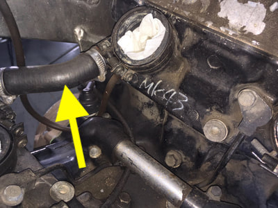
I've never come across generic replacements for the two large radiator hoses, but the small ones, two for the '86-87 and three for the '90-97, can be sourced locally. These small hoses live in a harsh environment and I get peace of mind by replacing them on my projects. They're located under the carb set and under the kick stand area. Before removing the various hoses, note how the hose clamps are oriented and replace in the same direction.
I've never come across generic replacements for the two large radiator hoses, but the small ones, two for the '86-87 and three for the '90-97, can be sourced locally. These small hoses live in a harsh environment and I get peace of mind by replacing them on my projects. They're located under the carb set and under the kick stand area. Before removing the various hoses, note how the hose clamps are oriented and replace in the same direction.
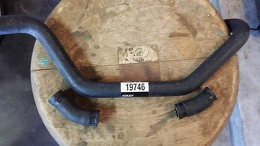
We're using a donor hose for the upper hoses under the carb set — Gates #19746, available locally, Amazon or eBay. Pictured are the two original upper hoses from the third- and fourth-gen bikes.
The procedure is to mark the new hose using the old sections, cut and install.
The procedure is to mark the new hose using the old sections, cut and install.
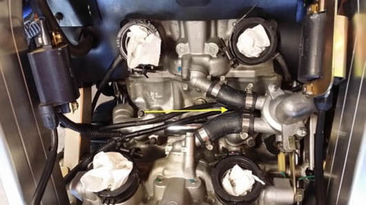
Here they are as installed on the '90-97.
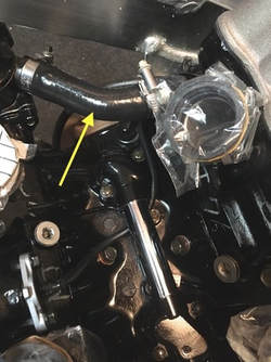
And here's the single hose on the '86-87.
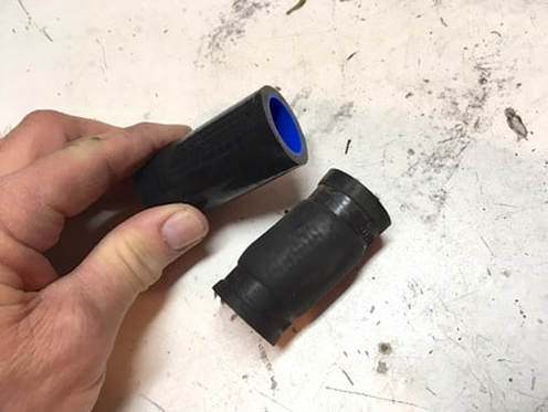
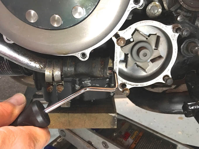
The lower hose is a 22mm (7/8") I.D. piece cut from a straight section of silicon coolant hose which I've sourced from Amazon. Replacement is straight-forward, but getting the old hose off can be a workout, made difficult as there's only about 20mm of space to remove/install a 70mm length of hose. I use my handy ARES hose removal tool (lower photo) and work my way around the hose ends.
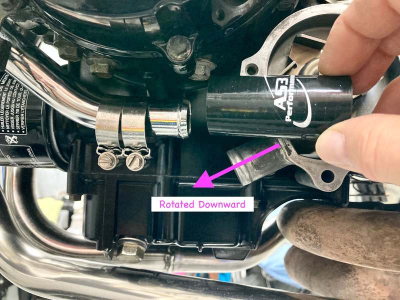
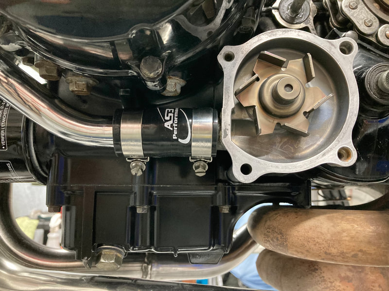
(Below) Here's a trick I use: Remove the water pump cover (this should be done in any case to inspect the water pump impeller blades). Pull outward slightly on the pump housing which allows the housing to rotate — this provides much more room to remove/install the hose. Slide the hose onto the chrome pipe, rotate the housing back into place, and slide the hose back onto the housing nipple. Before tightening the hose clamps, be sure to align the pump housing's bolt holes. Note: The pump housing can be entirely removed by pulling straight outward, but be sure the oil sump is drained down about a quart or oil will exit through the mounting hole. If you choose to remove the cover and/or pump you'll want to have new o-rings on hand — one for each — available from Honda.
If you leave the water pump in place, it helps to unbolt the hold-down bolt for the chrome coolant pipe coming down from the upper engine area and work the old hose backward onto the chrome pipe and force it off through the gap. You can also cut the hose into smaller pieces to remove it.
14. Reshaping A Chain Guard
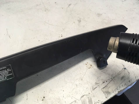
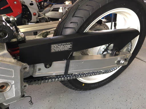
In their effort to "add lightness," Honda began to use more plastic during the 1980s. One part that changed from heavy metal was the chain guard. Over time, however, the long and not very well supported piece tends to twist or warp and begins to look a little wonky. I've found that if the right amount of heat is applied judiciously these plastic parts can be massaged nearer to their original shape.
This chain guard was deformed near the rear and actually rubbing on the rear sprocket. Using a heat gun I gently warm the area that I think will help reshape the part and then hold it (with thick gloves, it gets hot!) as it cools. This takes several gentle attempts. Be careful, too much heat and the part can deform or even bubble till it's no longer useable.
This process can be done on the bench or while mounted on the bike.
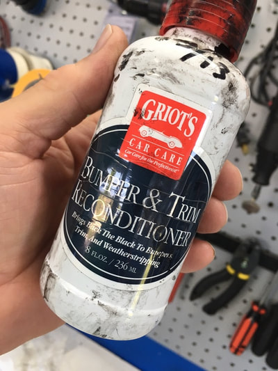
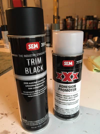
To bring back the original finish I lightly wet sand the chain guard and apply one or two coats of Griot's Bumper & Trim Reconditioner. This stuff works on all the black plastic parts, like the rear fender/license plate area. As an alternative for severely weathered plastic finishes, I paint the part with a plastic trim paint, like SEM Trim Black, available at body supply stores or Amazon.
15. Steering Head Bearing Replacement
When checking for steering bearing problems we're looking for roughness and especially a notchy feeling at the center point of the handlebar swing. Looseness can sometimes be dealt with by correctly adjusting the bearing tightness, but often as not the looseness has resulted in excessive wear to the bearings and their races.
These bikes were originally equipped with ball (roller) bearings, and there's nothing wrong with that approach in this application, but tapered bearings are an upgrade and should outlast the OEM bearings.
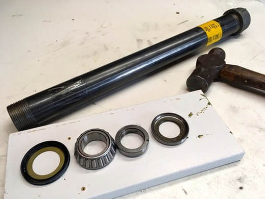
But how to remove and install the pressed-on lower bearing without the nice factory tools (or a handy machine shop equipped to remove and press the bearings)? Well, the old bearing inner race won't drive off, so I use a Dremel with a cut-off blade and very carefully slice the race with a diagonal cut, stopping just shy of cutting into the shaft itself. Right at that magical point the bearing race gives a little "bing" as it loosens its grip on the shaft — it can then be pried off with a screwdriver blade. In the photo above are (left to right) the new lower seal, the new bearing, the old inner race and the old outer race. I will use the old parts as adaptors to drive the new bearing in place.
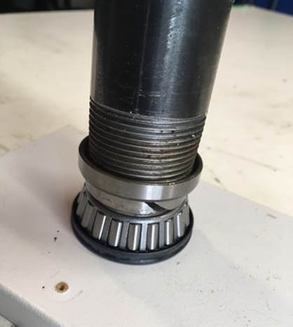
(Right) Here I have the parts stacked along with the driver tool — a length of black gas pipe or heavy conduit (with a cap installed to pound on). You can see the diagonal cut I made when removing the old inner bearing race; that cut is not quite all the way through the race. The old and new (inner) races are the same size so the old one makes a perfect driver adaptor to pound the new race onto the shaft.
However you accomplish driving the new bearing onto the shaft, remember that you can never press or pound on the roller cage itself — you have to drive onto the inner portion of the new bearing.
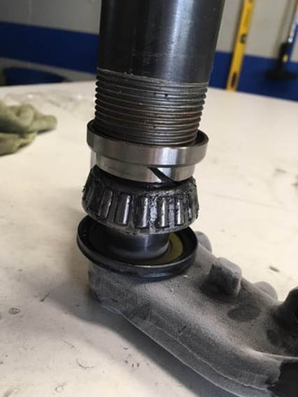
To prepare for driving the bearing onto the shaft, I first put the lower triple tree/shaft assembly into the freezer for several minutes to shrink the metal — frost is visible on the metal in this photo. I then quickly drive the freshly greased bearing into place. I drive the bearing till it just bottoms onto the seal but still turns freely. With the cooled shaft, the bearing slides on pretty smoothly but still requires several hard hits with a hefty hammer.
Job done. Reassemble onto the frame, install the forks, etc., and this project will be back on its own two feet — with a nice, smooth steering action.
16. Refurbishing Paintwork
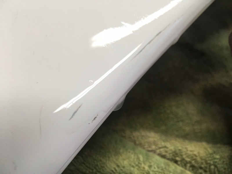
On my projects my goal is always to bring the original paintwork up to the highest level I can. Part of this might involve touching up nicks and scratches, but the real magic can be achieved with a process that I learned as "color sanding." The idea with color sanding is to remove just enough damaged paint to get down through the decades of scuffs, surface scratches and environmental damage — sun, pollution, petrified bugs, whatever.
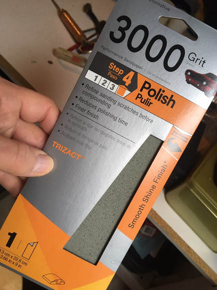
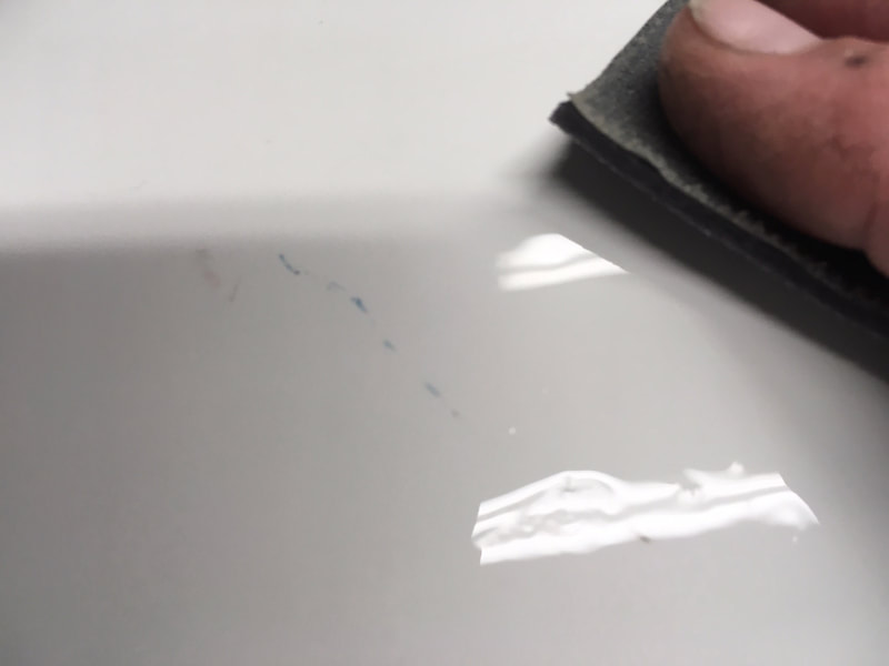
For the sanding portion of the process I use the finest grit I can get away with, working my way to a final sanding with 5000-grit. 3M provides wet-sanding paper and sponges up to 5000-grit. I begin with the 2000 or 3000 and go rougher only when necessary.
After cleaning the part to be color sanded, I fill a small, clean pail with fresh water with a few drops of dish soap added. With frequent dippings into the water, I gently wet-sand the entire painted area then wipe dry with a clean cloth to check my progress. A deeper scuff may require a stronger grit, remembering that the goal is to achieve the greatest effect but without sanding through the clear coat. This is especially true with pearl paints because the pearl coats are applied on top of the color and sanding away the pearl changes the hue of the finish color.
Practicing on an old part will give a good feel to how much sanding you can get away with before damaging the part with excessive sanding.
Below are a couple of examples of common fairing scuffs that will come right out with a gentle sanding.
(click on images to enlarge)
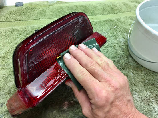
This process works just as well on plastic fixtures like tail light, turn signal and headlight lenses. Here I'm using 1000-grit paper on a tail light lens, which I will follow up with 1500, 3000 and 5000. Yeah, it's a lot of sanding.
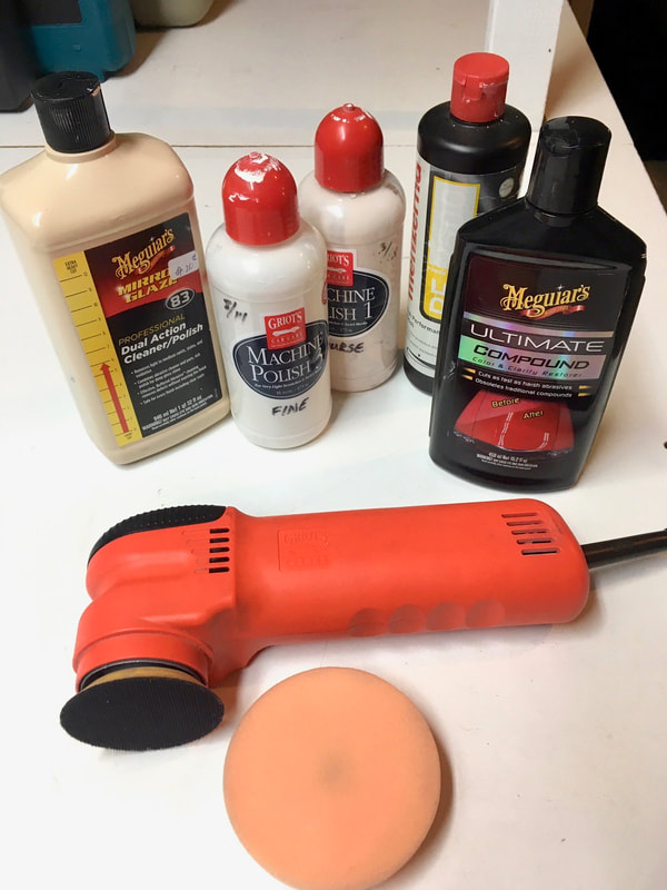
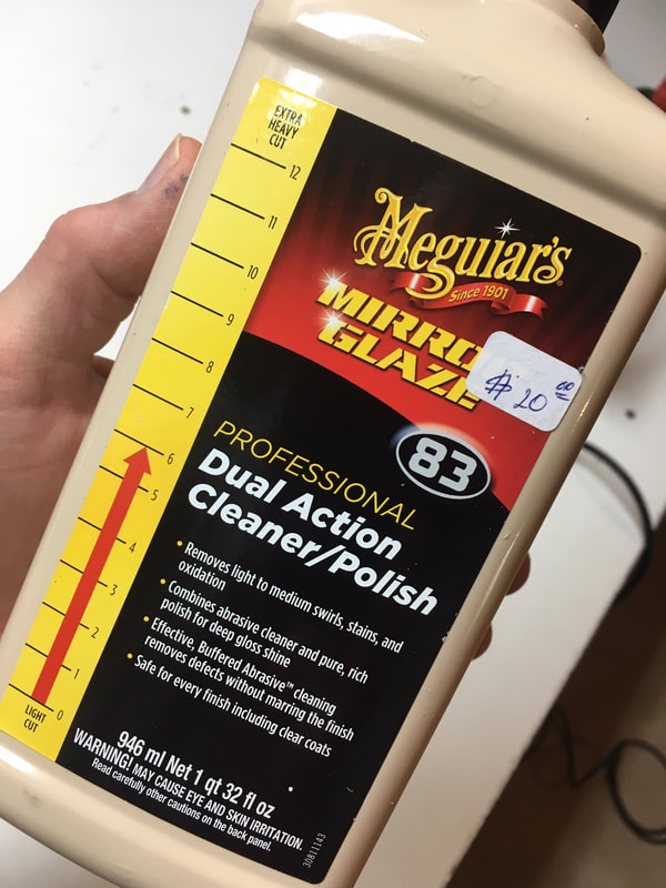
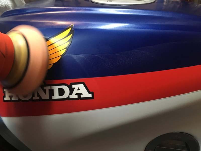
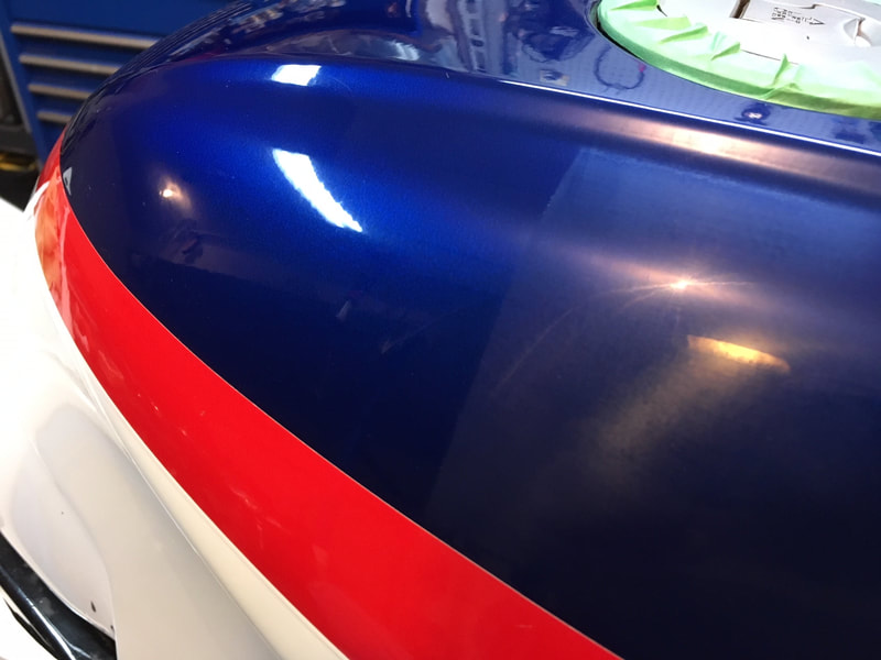
(Below) For the buffing portion of this process I use my Griot's Garage small orbital polisher with 4-inch buffing pads. I have a selection of compounds but my go-to is Meguiar's Ultimate Compound. If I think a stronger grip is called for, I'll buff first with Meguiar's Mirror Glaze #83 or similar. The lower right photo shows a sanded vs. buffed portion of the tank. I finish up with a quality wax, hand applied.
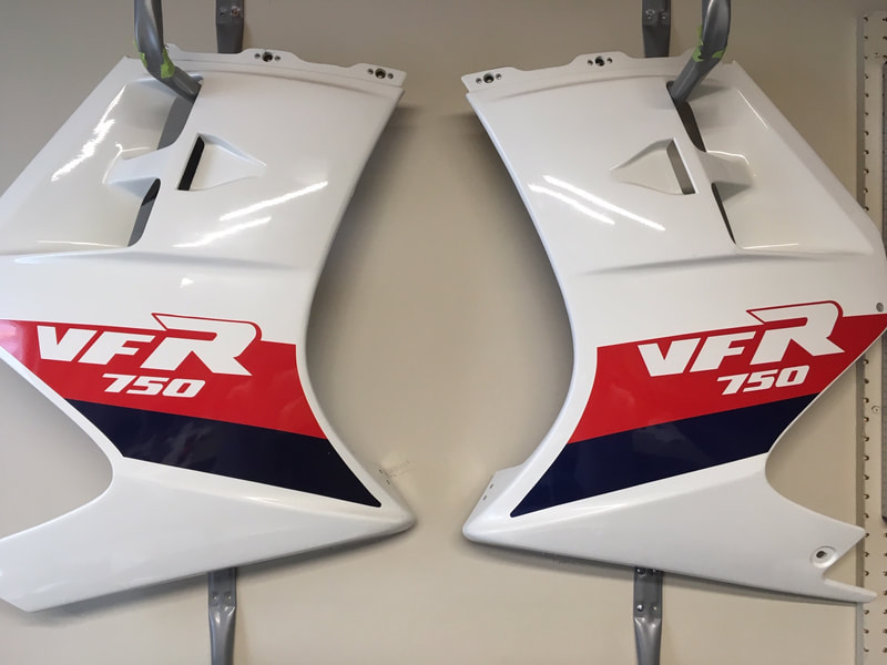
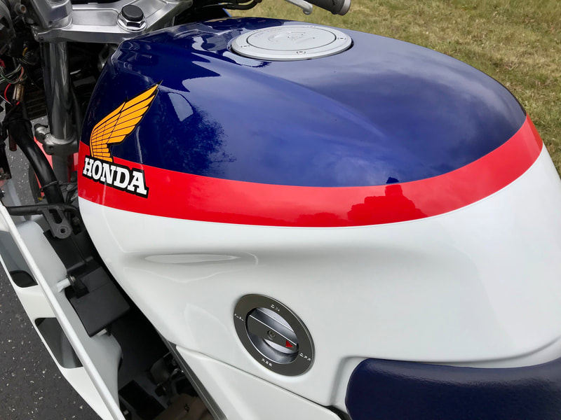
(Below) Some of the finished product.
17. Carburetor Removal
This tutorial will demonstrate carburetor removal on a 1986-87 VFR but 1st-4th generation bikes are very similar — consult your service manual.
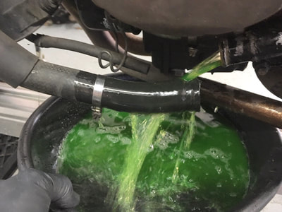
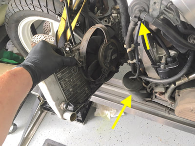
(Below) I start with radiator removal. I do this when I know that I'll be doing a valve adjustment check and having the radiator completely out of the way makes the process much easier. If you're only servicing the carbs this isn't a necessary step but it's not difficult, gives more working room and allows easier cleaning of the area, if you like. Drain the coolant via the lower radiator hose, remove the two hoses, unbolt the one upper and two lower mounting bolts, unplug the fan electrical connector (right side of bike, under headlight fairing), slide the radiator to the right to unhook from its hanger stud, then lower and remove the radiator from the left side.
NOTE: The photo on the right shows the emissions evaporative canister and other hardware, indicating a California-spec bike. I will show how to remove this system.
(click on any of the small images to enlarge)
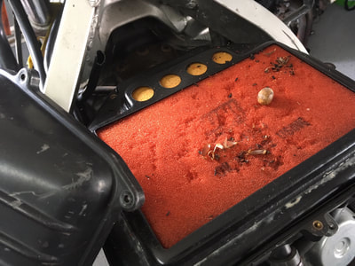
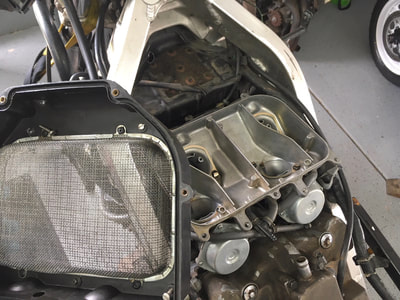
(Below) To begin the carb removal, remove the air cleaner and housing. Be prepared for anything when the cover comes off — in this case only a few mouse meal remnants were found, and no telltale mouse pee smell. That corrosive liquid will work its way downward into the carbs and wreak all kinds of havoc. These carbs look very clean. That's a UNI brand foam/oil filter and its life is over.
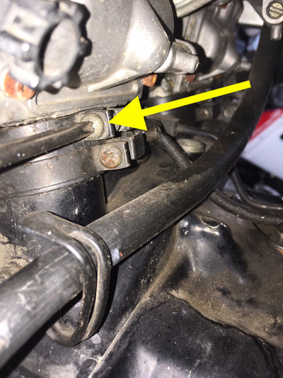
(Below) Next, I unscrew the four upper carb boot ("insulator") clamps. The lower clamps can remain tightened. Then loosen, but don't remove, the choke ("enricher") cable clamp. Leave the screw in place to prevent dropping the assembly now or during reassembly. Unhook the choke cable.
(Below) I then remove the two throttle cable bracket screws (left photo) which allow the cables to be slackened and easily removed — there's no need to touch the adjustment nuts. My first indication that these carbs have been dealt with before is that the lower bracket screw is not OEM.
(Below) Now the emissions stuff needs to be dealt with. I just cut the five hose connections in question, but they can also be removed if you wish to re-use the hardware. In this case, one of the vacuum hoses was cracked and leaking at carb #4, which highlights the issue with this old emissions hardware — lots of opportunities for difficult-to-find leaks. In any case, here's the connections.
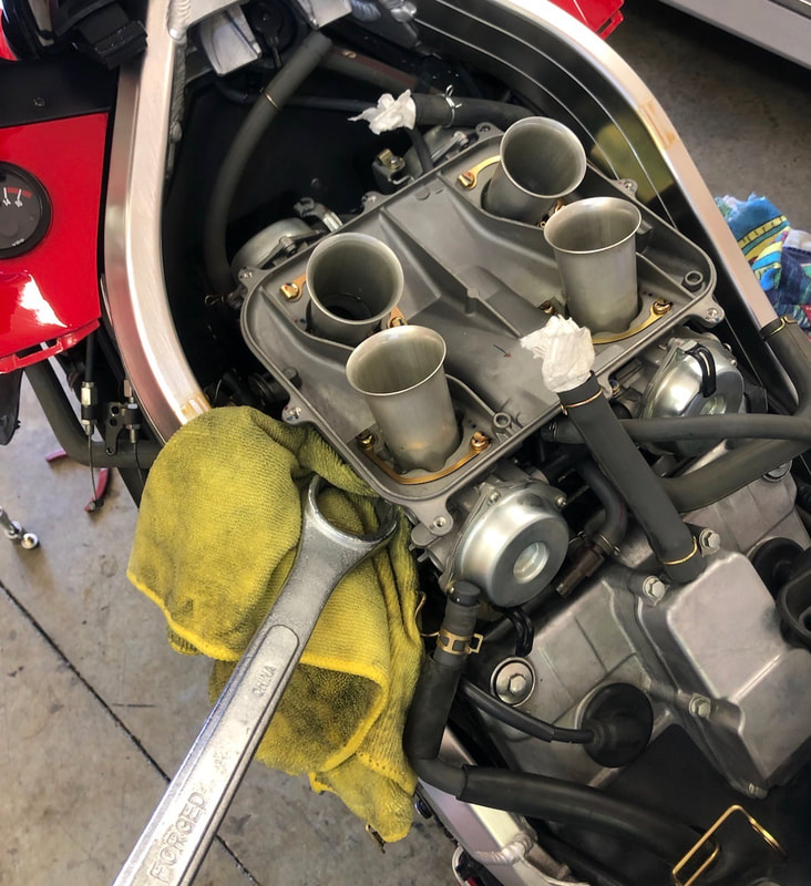
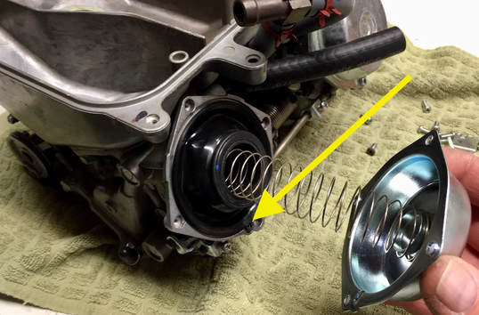
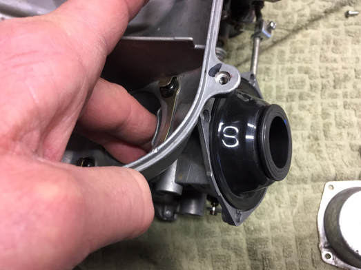
(Below) Let's get the carbs off. With everything loose, the rack is ready to lift off, but it will be stuck pretty tightly, so I gently lever the rear half free and then lift straight up to remove. I use a bent-tip lever with the yellow plastic scraper protecting the valve cover, and lever straight up under the rearmost carbs (#1 & #3), gently pushing upward at the lower point of the diaphragm cap (left photo). On the later models, try levering off to the side (right photo, courtesy of Juan O.). If they seem immovable, check that the boot screws are very loose and keep gently working them upward. Please resist the temptation to resort to a hammer. Once the rear is free, lift off the carb set.
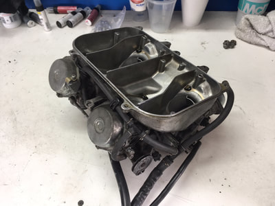
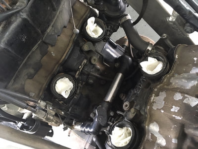
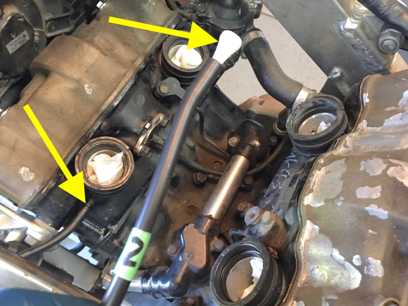
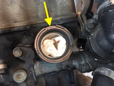
(Below) With the carbs on the bench, drain the float bowls into a container using the drain screws. Have a peek with a flashlight into the engine's intake tracts for skeletal remains or any other debris, then stuff some clean paper towel into the tracts. If you're going to clean the engine area, cover the intake holes with squares of cut-up plastic bag and zip-tie in place to keep water out. On the 2d-gen, the plastic covers from Edge brand shave cream cans fit perfectly.
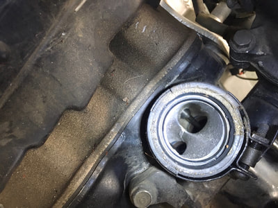
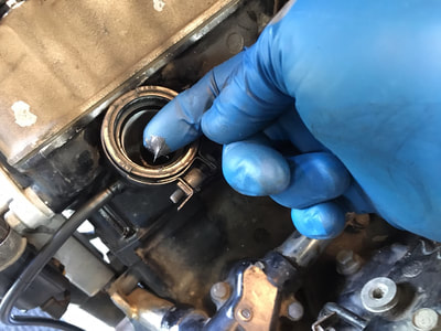
(Below) Here's what you should see in the intake tract; nice and clean with not too much carbon build-up on the valve stems. You may also see some blue scribbling on the engine block. Those are notes from the assembly line. Tip: Replace that little radiator hose before reinstalling the carbs. See tutorial #13, Small Coolant Hose Generic Replacement.
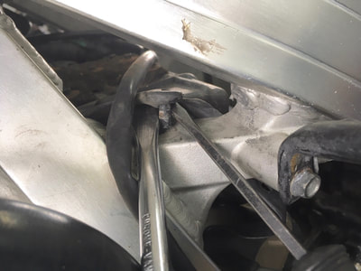
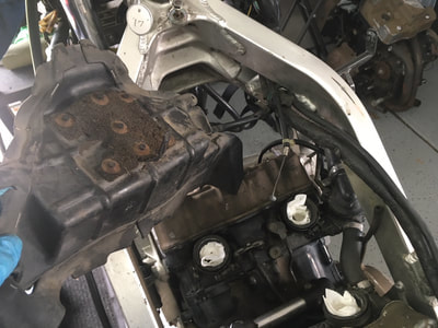
(Below) If you're planning a valve clearance check, you'll want to remove the air baffling above the front cylinders. This plastic cover is held in place by plastic "plugs" firmly stuffed into frame holes on either side. I use two flat-blade screwdrivers to pry the plug upward completely out of its hole. Shown here is the left side; the right is a tighter fit because of the wiring harness passing above it — just wrestle the harness out of the way. Lift the baffle on the left side, then out. Tip: Install in reverse: lower the right side into place first. That deteriorating brown foam stuff is sound deadening — as it disintegrates it will be sucked into the air cleaner housing. Feel free to scrape and scrub it off.
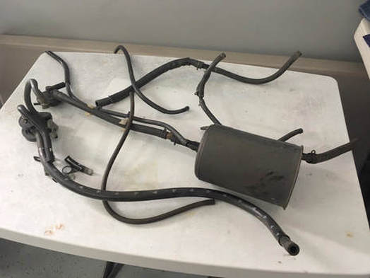
If you'll be removing the emissions hardware, follow each hose to its end point and unbolt the hardware. I'll toss it all and simply vent the line exiting at the rear of the carbs into the air; that's how it's done on the 49-state bikes. There's also five small vent tubes at the carbs which will need to be plugged. I'll cover that in the next tutorial.
Here's a look at the discarded hardware.
Job done!
Here's a look at the discarded hardware.
Job done!
18. Carburetor Disassembly, Cleaning, Reassembly
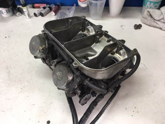
In this tutorial I'll show a basic cleaning of the carburetor set on a 1986 California-spec bike. All the generations of VFR carbs are similar, just a bit more complex with each subsequent generation — consult your service manual.
I begin with the carb set on a clean workspace with the fuel drained. For this basic cleaning the carb rack can be kept assembled to the plenum, and linkages left in place.
TIP: If you've got the carb set on the bench like this, seriously consider the benefit of replacing the fuel tube o-rings; see tutorial #1, which will also allow for a more thorough cleaning.
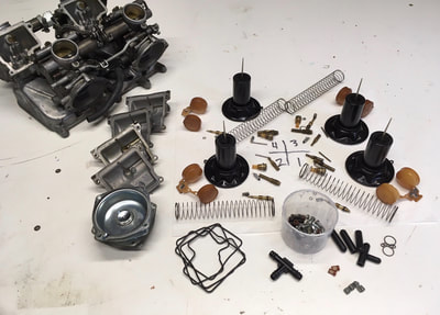
(Below) I first completely disassemble the components, separating them with respect to their individual carb; not really necessary, but probably not a bad idea. Inspect each part for condition as you remove it, paying particular attention to the slide diaphragms. I scrub the bare carb set in the sink with a water-based degreaser and hot water rinse, and give the small parts a dunk in an ultrasonic cleaner (if available). All the passageways are given a blast with compressed air and verified clear — I do this by attaching a short piece of hose to each orifice and blowing by mouth, listening for the escaping air. As a matter of course I replace the float bowl gaskets and air screw o-rings along with the fuel tube o-rings and fuel lines (see appropriate tutorials).
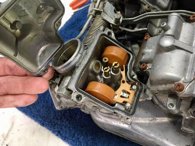
(Below) This carb set was pretty grungy on the outside, but surprisingly clean inside. Unscrew the two brass jets — using a proper-fitting screwdriver blade push firmly downward and give a sharp twist to break the jets loose; the soft brass will break if the wrong sized blade is attempted or if forced. The smaller is the low-speed jet and is susceptible to clogging from old fuel deposits. Verify it's clear or just replace — I always replace the #38 ('86-87) with a #40 (later years use #40 from the factory). Pull the float pins and lift the float and needle, noting how the needle hangs loosely on the float tang. That tang is bent slightly up or down to adjust the float during reassembly ('86-93, '94+ are non-adjustable).
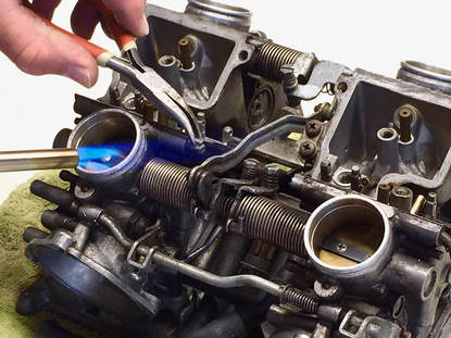
In order to remove the pilot screw adjusters, the factory caps need to be removed. This is made easier by applying heat from a small torch while gently pulling on the cap till it pops off. Be cautious with the heat, the metal used on these carbs has a low melting point. The caps are an emissions thing (to prevent owner tampering) and don't need to be reinstalled unless desired. The screwdriver groove will have some grunge in it so clear that out with a small blade.
In order to remove the pilot screw adjusters, the factory caps need to be removed. This is made easier by applying heat from a small torch while gently pulling on the cap till it pops off. Be cautious with the heat, the metal used on these carbs has a low melting point. The caps are an emissions thing (to prevent owner tampering) and don't need to be reinstalled unless desired. The screwdriver groove will have some grunge in it so clear that out with a small blade.
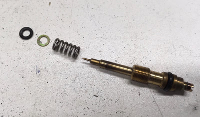
(Below) Turn out the screw, being very careful to avoid losing the spring, washer and o-ring inside. These little parts are NLA from Honda, though I have sourced replacements for the o-ring and metal washer (see Products page) and aftermarket rebuild kits should include them. I use a small nail or stiff wire with a bent tip to dig for the washer and o-ring if they're left stuck inside the hole. Inspect the needle for a bent or broken tip; it should look like the one pictured. NOTE: I have seen a video where the presenter indicates that these o-rings don't belong here — that's incorrect information.
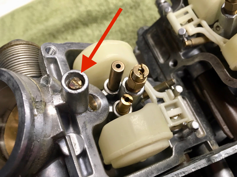
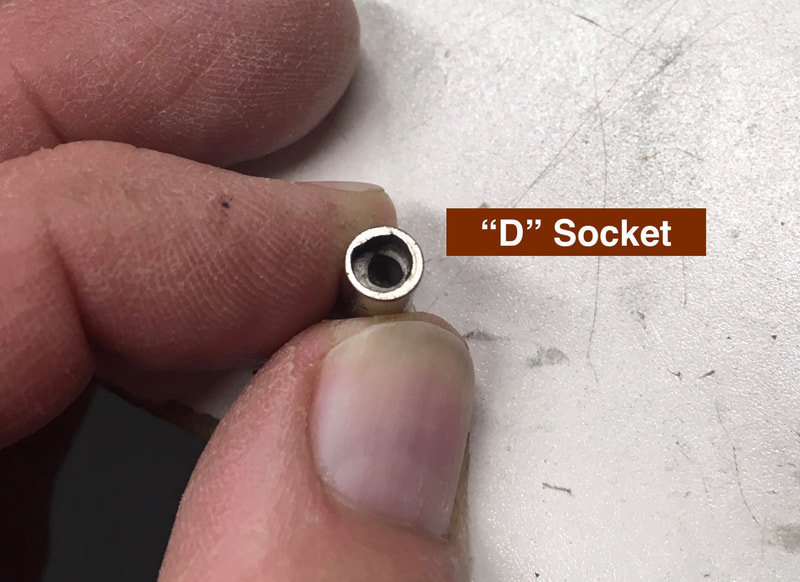
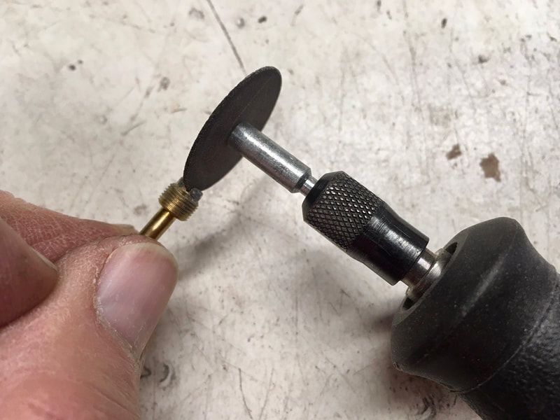
(Below) Here's the pilot screw location on the fourth-gen (1994-97). It requires a special "D" shaped socket. Once removed, I cut a groove into the screw head to allow the use of a straight-blade screwdriver in the future, but not necessary.
(click on a image to enlarge)
(click on a image to enlarge)
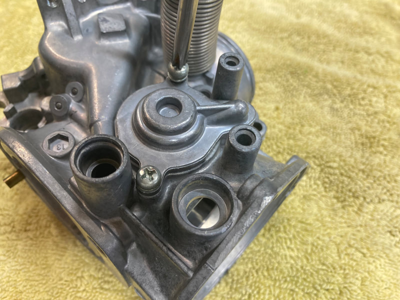
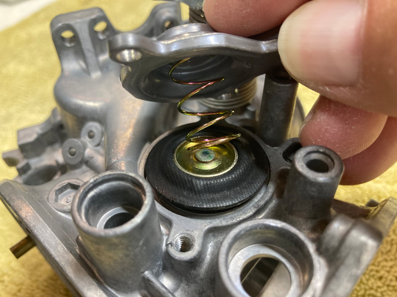
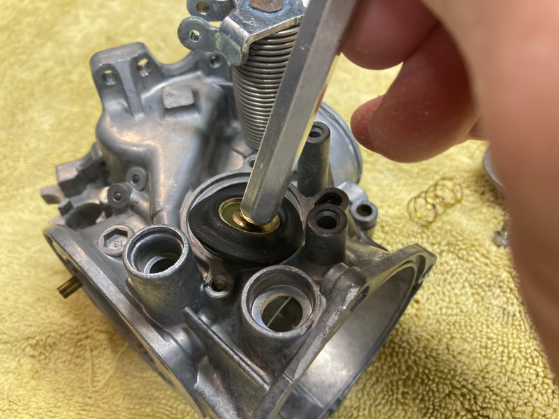
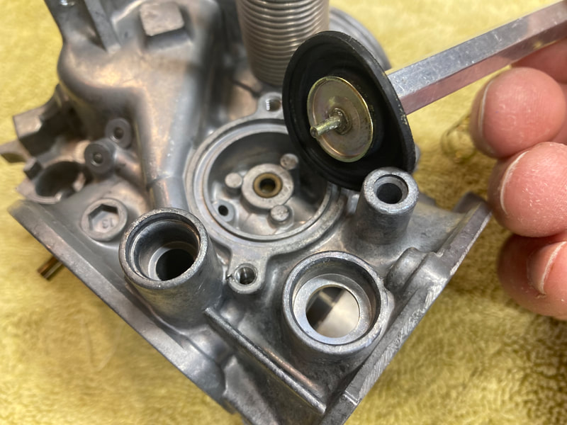
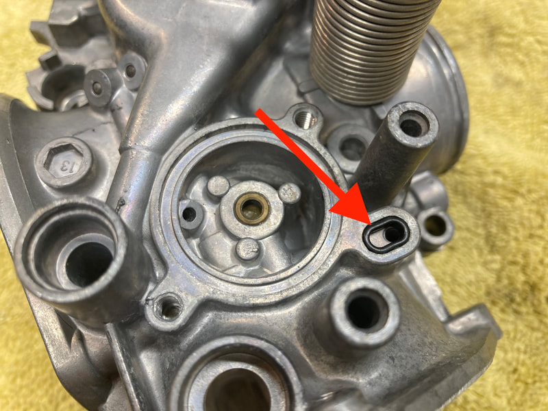
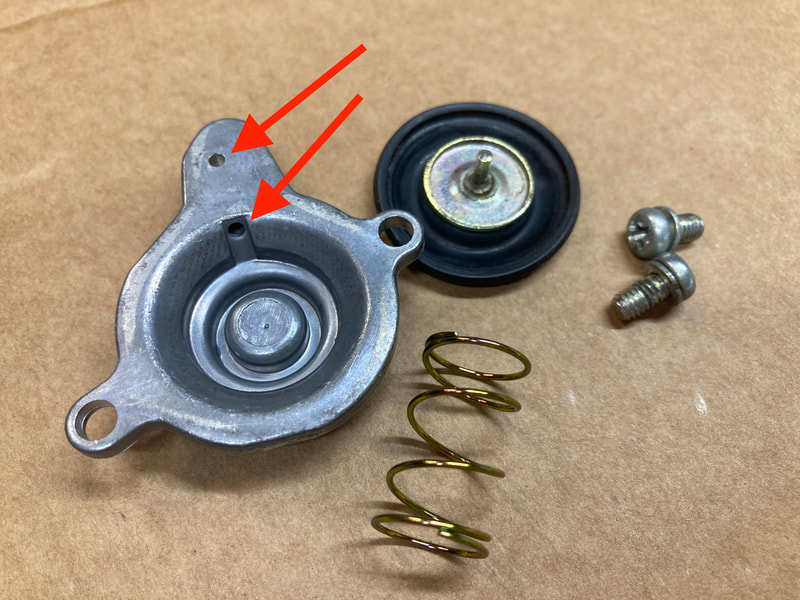
(Below) An additional component found on the 3d- and 4th-gen (1990-97) carbs is the Air Cut Valve assembly. The valve's function, as I understand it, is to prevent popping on deceleration (closed throttle). The valve is generally in reusable condition and servicing is a simple procedure.
We begin by removing the two cover screws. Inside we find a strong spring and the metal/rubber diaphragm (below). The diaphragm is usually slightly stuck in place, and rather than risk damaging the rubber, I use a small magnet to gently pull it free. Note the oval o-ring (arrow). These parts are no longer available from Honda but aftermarket kits are available. However, your parts are reusable if undamaged, so handle with care. Gently remove this o-ring for safekeeping during cleaning. I wash the parts and blow the air passage shown (two red arrows) clear with compressed air, along with the two passages in the carb body. Reassembly is simple, but that's a strong spring to hold pressure on while locating the screws.
We begin by removing the two cover screws. Inside we find a strong spring and the metal/rubber diaphragm (below). The diaphragm is usually slightly stuck in place, and rather than risk damaging the rubber, I use a small magnet to gently pull it free. Note the oval o-ring (arrow). These parts are no longer available from Honda but aftermarket kits are available. However, your parts are reusable if undamaged, so handle with care. Gently remove this o-ring for safekeeping during cleaning. I wash the parts and blow the air passage shown (two red arrows) clear with compressed air, along with the two passages in the carb body. Reassembly is simple, but that's a strong spring to hold pressure on while locating the screws.
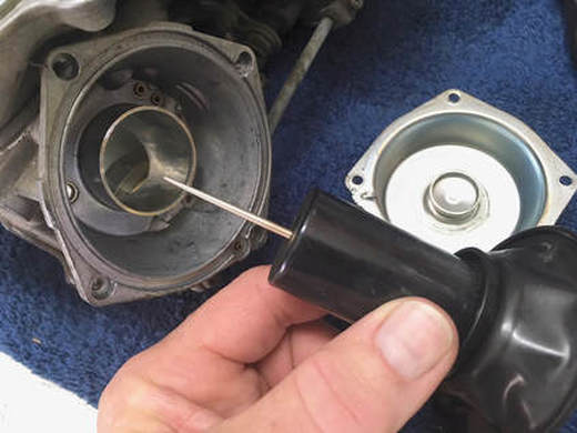
(Right) This main jet needle is stock OEM, which tells me that no jet kit was installed in this carb set. The needle assembly can be left in place, or the manual shows how to remove it using an 8mm socket in the event you want to replace it (bent needle or jet kit install) or add an additional shim (to lift the needle further). Inspect the diaphragm for holes by holding it up to a light source and gently spreading the rubber.
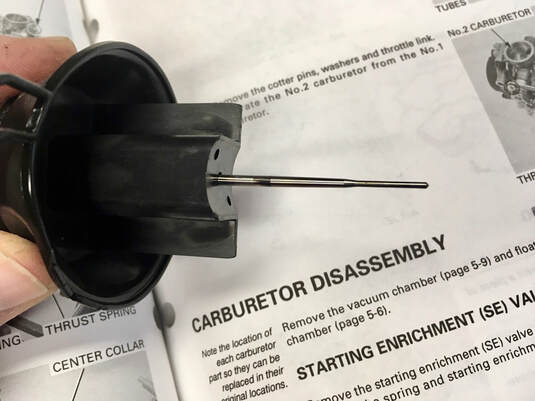
(Right) Here's a shot of an aftermarket jet kit needle, in this case a DynoJet needle on a 4th-gen "semi-flatside" slide.
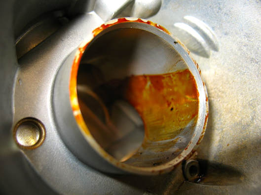
I like to clean up the slide bore with some fine steel or aluminum wool, especially if it looks like this. Here's the result of 20-year old varnished gas. These slides were very difficult to extract.
Note that the float diaphragm has a locating tab, with a corresponding depression in the cap (1986-93).
TIP: With your middle finger, hold the slide up in its bore while assembling the spring and cap with your other hand. This helps to keep the diaphragm seated during assembly.
Assemble the pilot screw (spring, then washer, then o-ring), and install by gently seating it, and then back off to specification, or I use 2 3/8 turns for OEM, and 2 3/4 turns with a jet kit ('86-87).
NOTE: These pilot screws meter fuel (not air), so turning out increases fuel, thereby enriching the mixture.
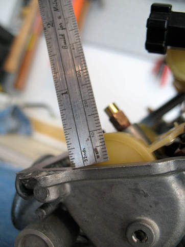
(Right) Check the float settings — the manual uses a special tool, but a ruler can be used (don't tilt the ruler like this!). I shoot for a 9mm height ('86-93), the '94-97 floats don't adjust.
Apply a bit of light oil to the pivot points of the throttle and choke linkages, and butterfly plates.
Be sure there's no left-over parts, and recheck all your screws; no need to over-tighten.
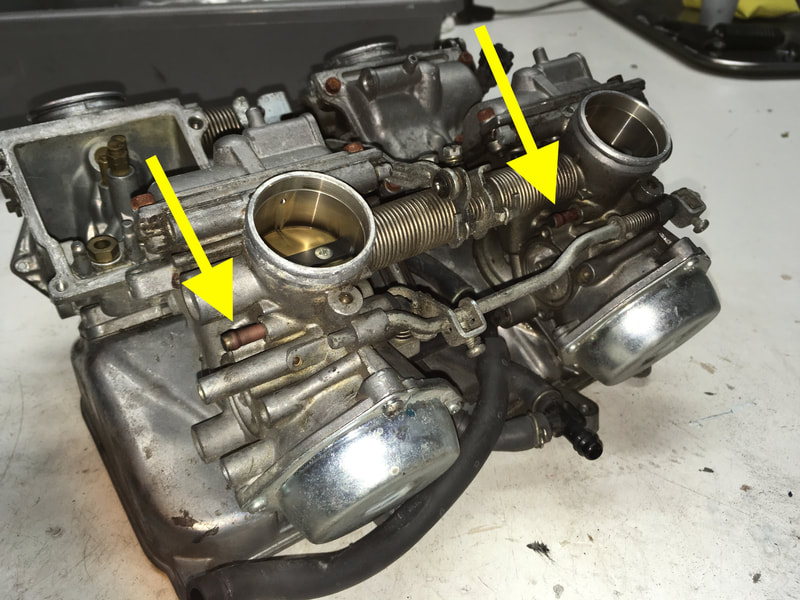
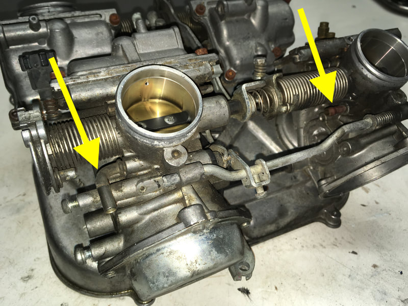
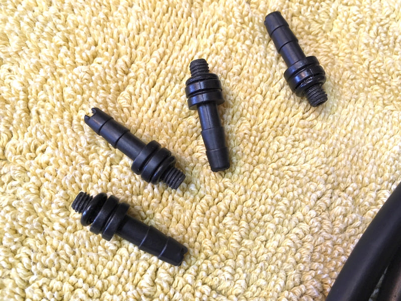
(Below) If applicable, the five California-spec vent tubes will need to be capped. I source 3/16" silicone caps from Amazon, secured using the original OEM spring clamps. For a more positive and permanent fix, I install sheet metal screws slathered with JBWeld or similar; one #6 for the small tube and four #8 for the larger ('86-87 shown). Your carbs are ready to be leak tested (tutorial #20), then installed.
(click on an image to enlarge)
(click on an image to enlarge)
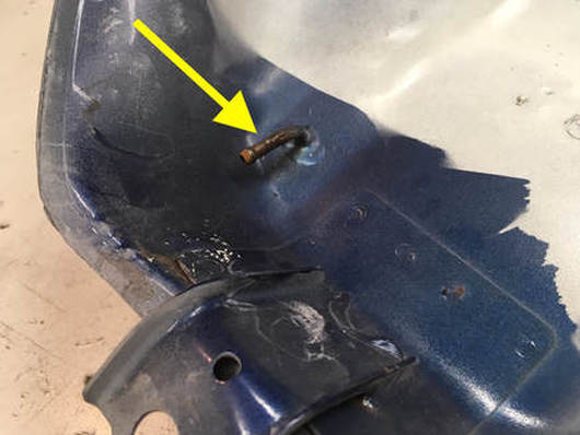
(Right) An additional aspect of California-spec bikes is the method of fuel tank venting. Instead of venting through the filler cap the CA bikes vent through a tube in the front underside of the fuel tank. DON'T PLUG THIS VENT. Check that the vent isn't clogged by back-blowing through it, then run an open hose downward through the front area of the frame and terminate somewhere safe and out of sight.
19. Preparing For Carb Sync
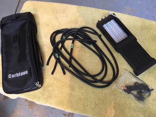
Before installing the carburetor set, and in anticipation of syncing the carbs, I'll want to attach the tool's adaptors and hoses. This is much easier with the carbs off the engine.
I use a Morgan Carbtune. After struggling with liquid manometer devices I discovered the Carbtune and it's found a permanent home in my toolbox.
I use a Morgan Carbtune. After struggling with liquid manometer devices I discovered the Carbtune and it's found a permanent home in my toolbox.
(Below) The adaptors are screwed into the intake manifold vacuum ports. Remove the screw and washer in each manifold. On California-spec models and 1990+ models, two or more of the ports will have hose adaptors in place for the emissions hardware. Remove and later replace with solid screws if you're removing the emissions hardware, as I am on this California-spec 1986 VFR750.
(Below) The adaptors are lightly screwed in place (Morgan now uses brass adaptors); no need to compress the rubber o-ring beyond what's needed to make a seal. I then connect the hoses to the adaptors, which I've labeled #1 through #4, and plug the ends with golf tees. Later, when I'm ready to sync, I'll remove the tees and connect to the gauge.
Ready for carb installation.
Ready for carb installation.
20. Carburetor Installation
As your shop manual likes to say, "installation is the reverse of disassembly." Which is true, but here's a few tips I've learned over the years.
NOTE: I will be syncing these carbs once the engine is running, so before proceeding with this install, I've connected the sync tool's vacuum hose adaptors and hoses — see the previous maintenance tutorial, "Preparing For Carb Sync" for details.
TIP: Check your carbs for leaks before installing: see my technique at the bottom of this post.
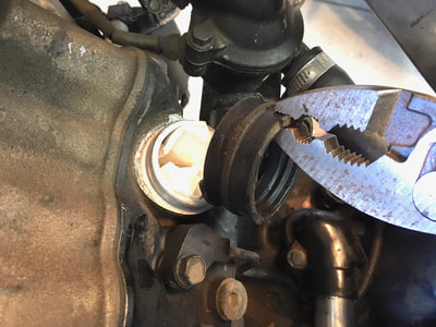
If your carb insulators (manifold boots) are hardened with age, simplify your life by installing fresh boots, the '86-87 boots are still available from Honda, later years from the aftermarket. First remove the lower clamps and, with a large pliers, give the old boot a firm tug to remove. Clean up the area and push the new boot into place, noting that the groove adjacent to the word "Carb" is oriented to 12-o'clock (below). Install all eight boot clamps and thoroughly tighten the lowers. TIP: I orientate '86-87 clamps to the left which I find makes access easier, using a long shaft screwdriver.
(Below) I wipe a film of grease or something similar on the lip of the boots to help the carbs slip into place. The upper clamps should be loosely in place. Place the carb set square to the front boots and push firmly down till seated in the front boots, verifying with a flashlight that they're seated. To get the rears in place, while standing on the left side of the bike, I maintain downward pressure with my left hand while running the blade of a flat screwdriver along the inside of both rear carb boots with my right hand. If your boots are fresh and supple they will "pop" into place after repeating the screwdriver trick two or three times. Tip: if you're in a cold environment, adding heat to the boots with a heat gun will help soften the boots. Resist the temptation to resort to hammering on the carb set to seat the rear carbs — you'll likely break a chunk off the metal plenum.
(Below) Tighten the upper boot clamps making sure that the clamp is square in its groove all the way around. Use a flashlight to verify this as you're tightening the clamp. The 1990+ clamps have an upgraded design to hold them in their grooves, but the earlier models don't. Next, Install the throttle cable ferules, then the cable bracket's two screws. Install the choke cable ferule, adjust to get slight tension on the cable, then tighten into its clamp. Tip: A long screwdriver is invaluable to reach the right side carbs ('86-87), and a JIS screwdriver is always recommended.
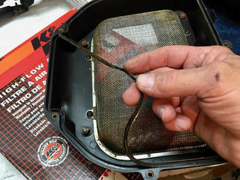
Finally, install the complete air filter housing along with the type of air filter that you plan to use. (Right) In this case I'll be using a K&N filter so I'll remember to remove the rubber gaskets in both the top and bottom air filter housings. The K&N won't fit correctly with those gaskets in place. I'll keep them in case a future owner wants to go back to OEM.
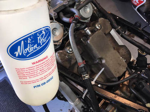
(Right) At this point I'll connect the fuel bottle direct to the carb intake line in preparation for engine start. If you do this, disconnect the fuel pump power supply at its connector just above the pump. The pump relay can remain connected.
You can also use the fuel bottle or the bike's fuel tank with all its plumbing, pump, relay, etc. hooked up.
You can also use the fuel bottle or the bike's fuel tank with all its plumbing, pump, relay, etc. hooked up.
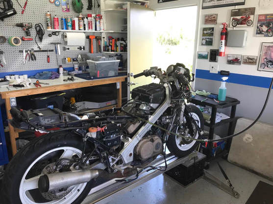
With the radiator reinstalled (and filled), double check all your connections, connect the battery, and we're ready to hit the magic button!
Allow the engine to warm for about ten minutes, shut down, and connect the sync hoses to the tool to sync the carbs; see tutorial #21, "Carburetor Synchronizing."
Leak Check
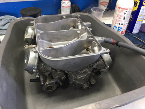
Here's a tip I learned the hard way. You'll want to check your carb work for leaks, and having the carbs completely mounted is not the best time to do that — if there's a leak it'll be dripping all over your engine or, worse, overflowing through the vents directly into the intake manifolds and down into the engine. Save yourself all that potential grief by checking the carbs on the bench.
I simply place the carb set into a large tub (a cat litter tub is perfect), connect the fuel bottle, open its spigot, and let them sit for at least a few hours, overnight is best. Any leaks are contained, and because the carbs are off the bike, finding and fixing a leak is less painful.
21. Carburetor Synchronizing
For our purposes carb syncing is the process of setting the individual carb's butterfly valves to open at the same time. The effect is to provide equal amounts of air (and thus fuel) giving us the most power and smoothest operation. This is a crucial step in tuning any multi-cylinder engine, but especially highly tuned, high-performance ones like the V4 Interceptor.
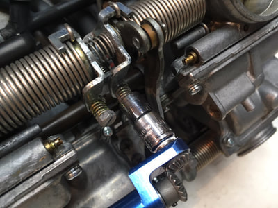
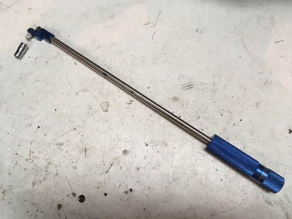
It's a simple concept with the only difficult part being actually getting to the set screws. That's where the Motion Pro 90-degree Hex Driver comes into play.
It's a simple concept with the only difficult part being actually getting to the set screws. That's where the Motion Pro 90-degree Hex Driver comes into play.
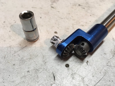
(Below) For the VFR, I snap on a 7mm socket to fit the adjuster screw. A straight blade screwdriver socket will also fit but is much more difficult to actually use. The reason is that we'll need to fumble around under the carb set to find the adjuster. The socket is just a more positive engagement. The tool doesn't hold the socket very well (seems to be common with Motion Pro socket tools) so I wrap a bit of teflon tape on the base to help out.
With the engine warmed and idle set at about 1200 RPM, and using #2 carb as a (non-adjustable) base ('86-93, #1 is the base for '94-97), adjust the other three to match. I do this first at idle and then check at a steady higher RPM, about 3000. When I'm happy with the adjustments, shut the engine down, allow it to cool a bit and remove the vacuum port adaptors and screw in the plugs with their washers. The sync adaptor for carb #3 is difficult, but not impossible, to reach with the carbs installed ('86-87).
There's some good video tutorials on YouTube for more syncing tips.
22. Chain Slider Fix ('86-87)
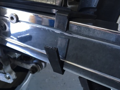
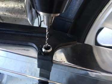
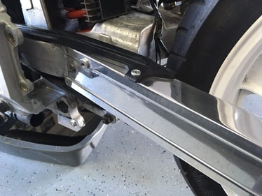
There's many small details on these old VFRs that can help make your bike stand out above the rest. One of these is the rubber chain slider on the '86-87 models. The rear of the slider is secured to the swingarm by this loop (below), which is nearly always broken, like this one. The slider is NLA from Honda and, in any case, requires the removal of the swingarm to replace. I've come up with a solution which makes life easier and provides a more positive and permanent attach point.
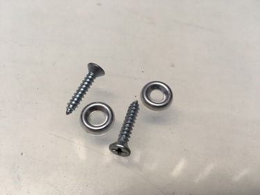
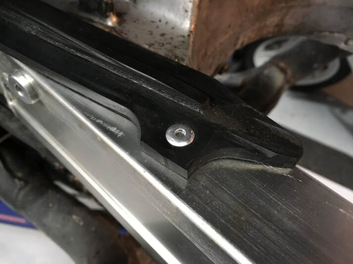
(Below) I'm going to secure the top and bottom of the strap to the swingarm with these screws and upholstery washers, then trim the excess strap. A slick alternative is to use aluminum rivets; I use a 3/16" with a minimum 1/4" grip length.
(Below) I'm going to secure the top and bottom of the strap to the swingarm with these screws and upholstery washers, then trim the excess strap. A slick alternative is to use aluminum rivets; I use a 3/16" with a minimum 1/4" grip length.
(Below) I simply locate the washer near the mid-point of the swingarm and drill the appropriate sized hole, install the screw & washer and trim the rubber strap. Repeat for the lower strap. Note that access for the drill will require that the swingarm is either removed or has full movement, requiring the subframe raised or the shock removed — or a right-angle drill avoids this.
Here I've used the rivet approach. Once the chain guard is in place, this repair helps clean up the look of the swingarm.
23. Brake Caliper Disassembly
Our brakes are one of the most critical but often most neglected systems on a motorcycle. When you add in old age and long periods of disuse, well, your brakes will pay the price. With unknown histories, I go through the complete brake systems on all my projects, and I begin with a complete disassembly of the three calipers.
The heart of the calipers are the pistons, which are actuated by hydraulic pressure. This high pressure is contained with the caliper by a double seal. The seals are small square section rubber rings, two per piston, and serve not only as a means to protect the clean brake fluid by sealing out the elements, but also act as a mechanical spring, deforming as the piston is forced out during braking and then pulling back very slightly on the piston when pressure is released, allowing the brake pad to release its hold on the disc. The seals may look simple but are precision items and should be treated as such. They're still available from Honda and aftermarket suppliers, like K&S, for about $20 per caliper.
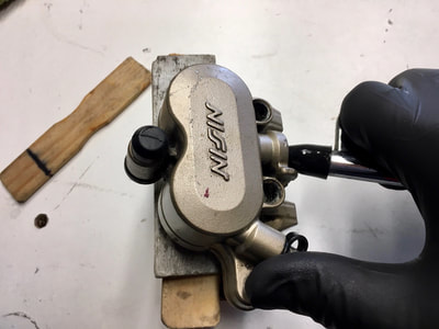
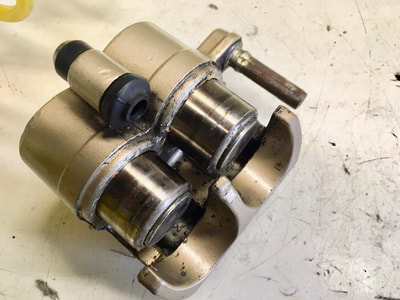
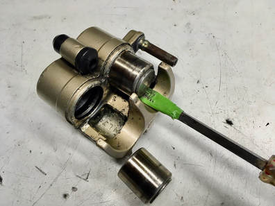
The pistons themselves are also available but, unlike the seals, can often be reused — provided they're removed without damaging their polished surfaces. Two effective techniques are hydraulic pressure (pump the brake lever) and compressed air pressure. The trick in both cases is to do so in a controlled manner. One of the two pistons will want to come out more easily than the other, leaving one piston hopelessly caught in its bore. Here's what I do:
Using precision shims cut from the finest paint stir sticks, I begin removal with a full stack of shims, removing one shim at at time, as I add pressure, till the final shim has the pucks equally near their exit point. Remove the last shim and the final blast of air or hydraulic pressure will force out one of the pucks, leaving the second one to be removed manually. BE VERY CAREFUL DURING THIS FINAL PUSH. If you're using air pressure the piston can shoot out of the bore like a bullet, ricocheting off you or the shop walls, damaging itself or anything in its path, including you. If you're using hydraulic pressure the brake fluid will projection vomit everywhere. Just one of the many joys of playing with old bikes. In either case, cover the pucks with a shop towel before adding air or hydraulic pressure.
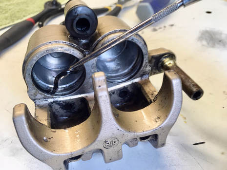
(Below) To work the second piston free, I gently rock it back and forth using finger pressure and a wrapped screwdriver blade. Alternatively, I reinsert the removed piston just enough to engage the first rubber seal, hold it in place with a finger and apply gentle air or hydraulic pressure to force the remaining piston the rest of the way — this might take a few tries. It can be stubborn, but persistence pays off. Next I use a dental pick to carefully extract the seals. The next steps are cleaning, inspection and reassembly, but you're through the tough part.
NOTE: Don't forget the slider pin inside that bore pictured on the caliper's upper side in the two lower photos, see tutorial #2, "Rear Caliper Sleeve Replacement."
NOTE: Don't forget the slider pin inside that bore pictured on the caliper's upper side in the two lower photos, see tutorial #2, "Rear Caliper Sleeve Replacement."
24. Mirror Refurbishing
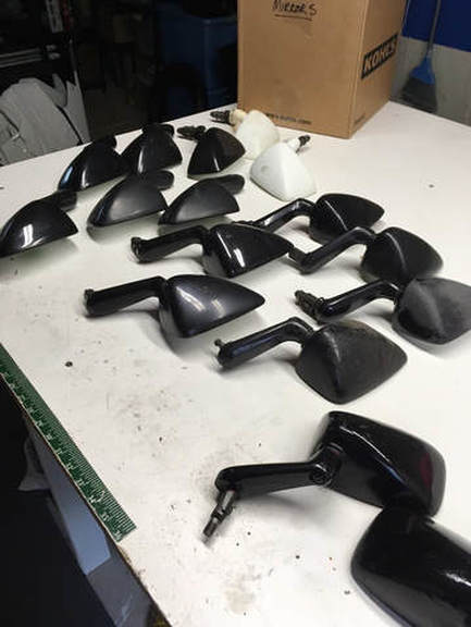
Our mirrors take a beating. Garage rash, tip-overs, whatever...after a few decades they can end up in pretty rough shape. Another issue specific to the second-gen mirrors is that the decorative plastic sheathing covering the mounting arm is susceptible to cracking from ham-fisted owners. I have a selection of mirrors in varying states, all needing complete refinishing before being used on one of my projects.
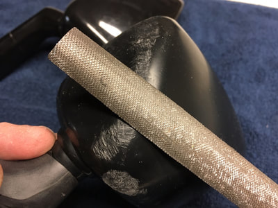
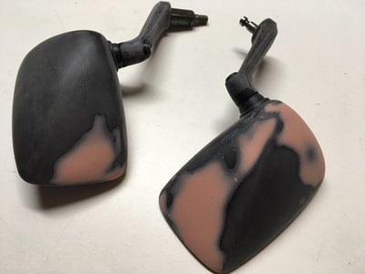
Recently I selected three sets of mirrors, one set with intact mounting arms and the others with cracked plastic sheathing. My solution for the damaged arms is to remove the sheathing, sand and repaint. The actual arm beneath the sheathing is some sort of hard, solid plastic material, which is easily smoothed, primed and painted.
Recently I selected three sets of mirrors, one set with intact mounting arms and the others with cracked plastic sheathing. My solution for the damaged arms is to remove the sheathing, sand and repaint. The actual arm beneath the sheathing is some sort of hard, solid plastic material, which is easily smoothed, primed and painted.
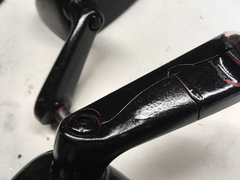
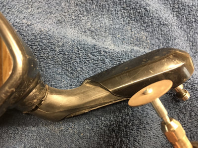
(Right) Here's a look at a typical damaged mounting arm. This set had also been crudely repainted at some point in the past.
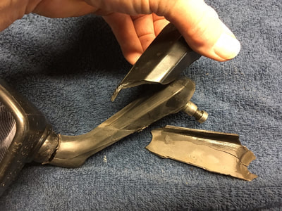
(Below) I begin by using the Dremel with a cut-off disc to cut the sheathing into smaller pieces, being careful to gouge the underlying casting as little as possible. I then crack the plastic bits away with a screwdriver and pliers.
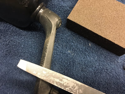
(Below) Next, I file the ridges smooth and fill any imperfections with body filler followed by wet-sanding with 320-grit.
(Below) Next, the mirror housings will need to be prepped for repairs and paint. I attack heavy damage with a couple of grades of files, followed by a few grades of sandpaper, finishing with 320-grit. The entire assembly is then filled, sanded, primed and finished with color and clearcoat.
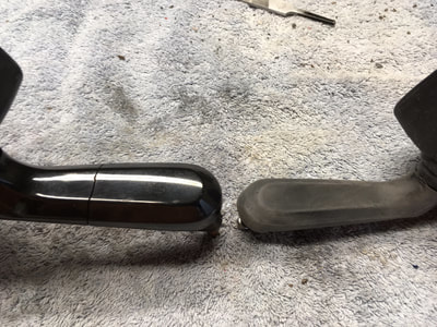
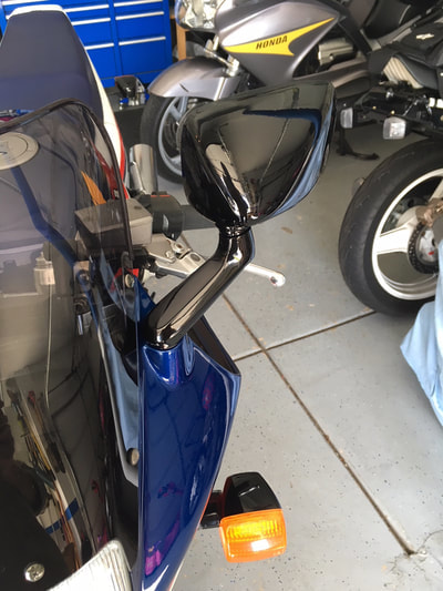
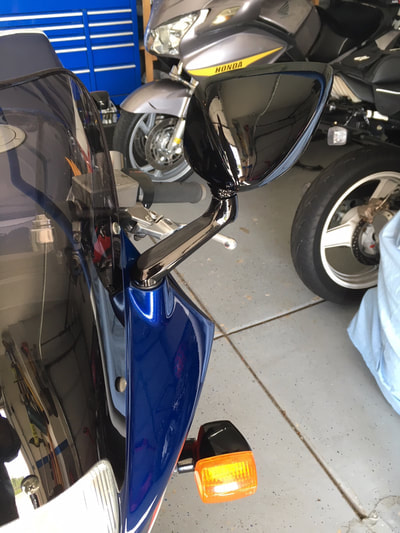
(Below) Job done! Here's a comparison shot of the refinished mirrors, with (left) and without (right) the mounting arm sheathing.
25. Gas Siphoning Made Easy
I have the need to empty fuel tanks on a regular basis, whether it's a new project with stale gas left in the tank or simply wanting to lighten the tank to make removal easier and safer. One method on the VFR is to use the fuel pump, diverting the outlet line into a gas can, but this is best for a smaller amount of fuel as it takes awhile and taxes the pump. There's also a selection of siphons and pumps available online, but I prefer to keep it simple and safe, so I use the ancient principal that liquid seeks its own level. All this requires is a length of plastic tubing.
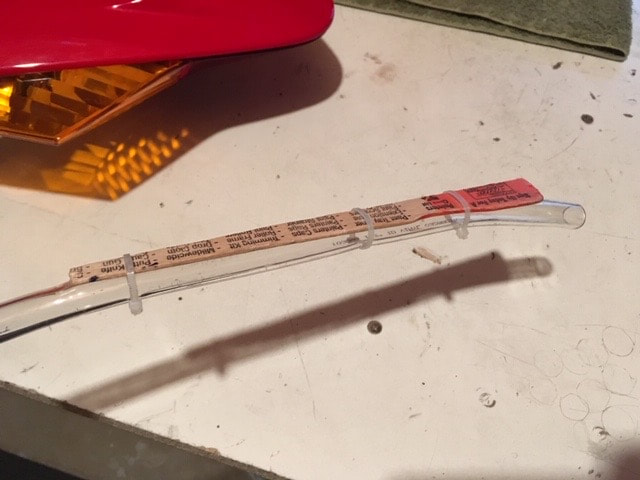
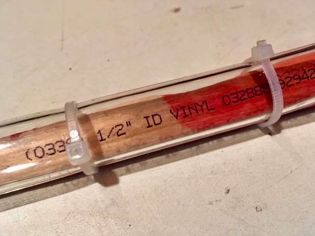
One of my favorite YouTube guys is Paul Pomerleau. He explains stuff in a simple, down-home way...often in his house slippers! A modification I find useful is to zip-tie a length of narrowed paint stick to the fuel tank end of the hose, which takes out the curl and allows the tube to be positioned at the very bottom of the tank.
Be aware that this technique empties the tank quickly, so be ready to raise the gas can/tube above the fuel tank (to stop the flow) to switch to a second gas can. An alternative is to crimp the hose shut with a locking pliers. If you have only one gas can, pause the flow by securing the raised tube to the handlebar (or crimp the hose shut) and empty the gas can into your car (assuming the fuel is useable).
(click on an image to enlarge).
26. Plugging The PAIR Ports
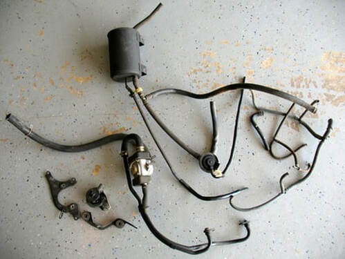
Back in the day there were both "49-state" and California-spec bikes. The difference is in the plumbing — emissions plumbing, that is. These were part of the first wave of "EPA" bikes in the U.S. Eventually, all VFRs would incorporate PAIR ports as part of the required emissions.
The various bits of hardware, shown at right, accomplished two things (as far as I can tell). The charcoal canister cleaned up some of the carburetor venting fumes and the PAIR air pump injected air near the exhaust ports.
The idea was that the injected blast of fresh air will give any unburned exhaust gases a chance to burn up after leaving the engine, thus producing cleaner exhaust readings at the tail pipe. On the next generation of VFRs, these injection ports were added to cylinders #1 & 3 as well. The whole contraption was obviously effective enough to satisfy the feds back in the day, but 35 years later it all produces a lot of potential leaks and no way to test whether it actually still functions as intended. So, I vote to eliminate the system as a whole.
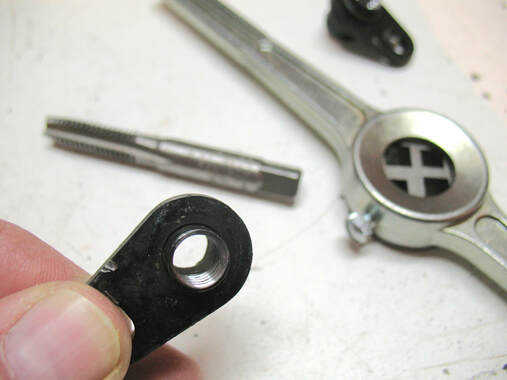
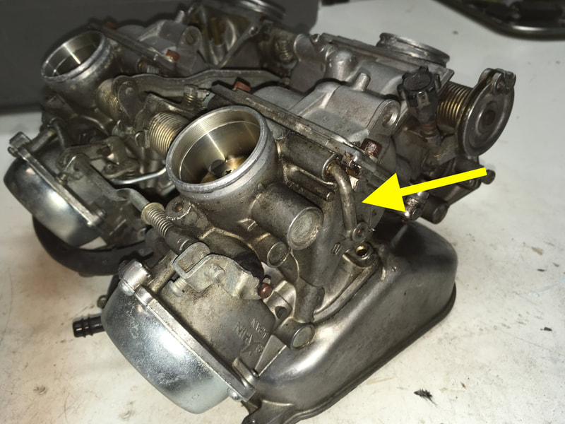
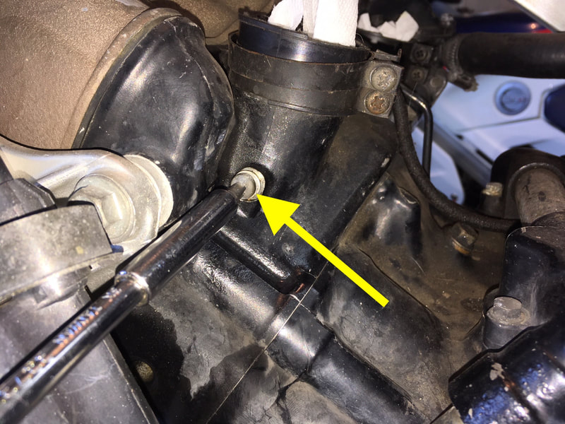
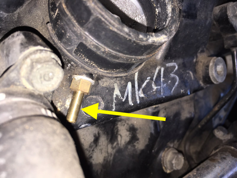
The fix is pretty simple. Remove all the hardware, plug the carb ports (five total) and plug the PAIR injection ports.
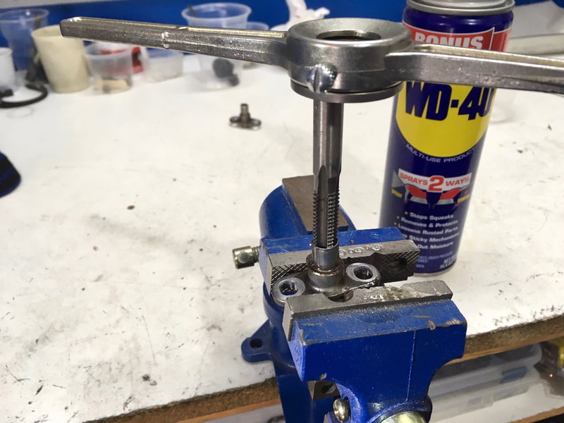
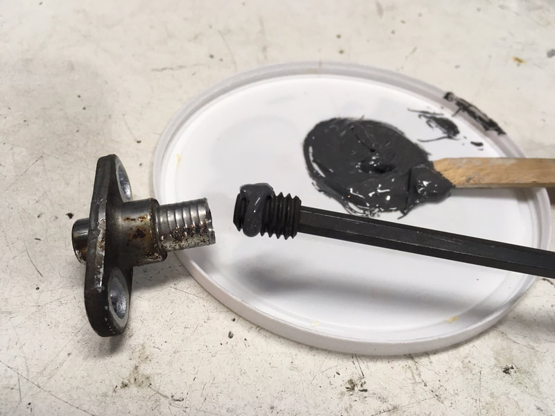
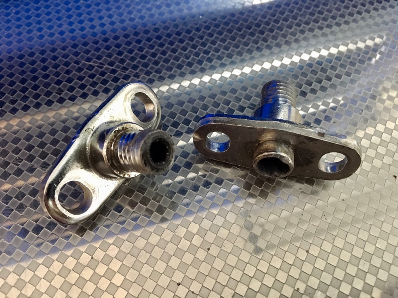
My cheap and simple fix for eliminating the PAIR injection port is to cut the port's metal tube off, leaving about a 1/2" section, tap a course 3/8" thread into the (former) air passage, fit a shortened bolt coated with gasket cement or JB Weld, give it a coat of black engine paint and bolt it back up to the engine block.
My cheap and simple fix for eliminating the PAIR injection port is to cut the port's metal tube off, leaving about a 1/2" section, tap a course 3/8" thread into the (former) air passage, fit a shortened bolt coated with gasket cement or JB Weld, give it a coat of black engine paint and bolt it back up to the engine block.
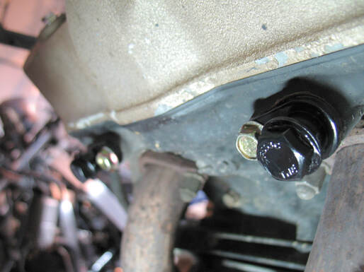
(Right) Here's the installed plugs on a 1986-87 VFR 700/750.
(Below) Here's some photos from the same operation on a 1995 VFR. The allen screws are a little more elegant plug solution.
(click on an image to enlarge)
27. Eliminating The Stator Wiring Connector
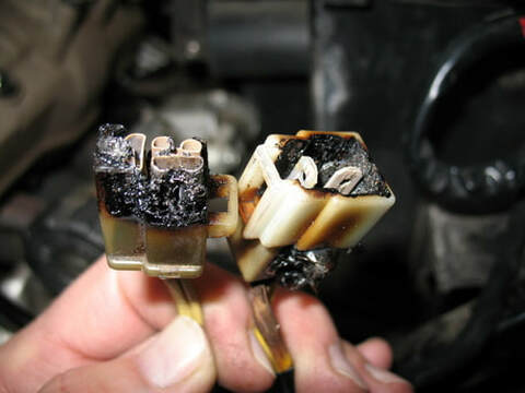
(Right) Well, this can't be good.
Here we have a fried 3-wire connector between the stator leads and the regulator/rectifier. When the R/R fails the wires heat up (they carry a large amp load) and that heat makes these blade connectors act like a fuse and here's the result. This situation can also roach the stator.
This is a fairly common problem with this era of Japanese bikes and Hondas are not exempt. As late as 2005 Honda had to issue a VFR800 recall for this sort of thing.
The problem stems from an inferior R/R design and is way more complicated than my analog brain can follow, but the real fix is a better R/R, like from Rick's. And here's a helpful thread on the subject from VFRWorld.com.
But for now we need to fix this mess.
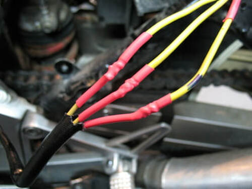
And here's my repair. No connectors for me — I hardwire the stator leads with solid soldered joints. I like to leave about 5 inches of excess wire so there's enough for a future repair.
NOTE: The three yellow wires are not particular about their partners — they can be reattached to any one.
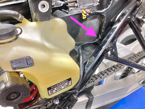
After wrapping the individual joints, the entire length is taped and tucked into place. TIP: If you heat the length of the newly taped portion with a heat gun the harness can be formed to a desired routing, in this case behind and under the fuel pump (RC24/26).
All that's left is to fire the engine and see if the electrons are moving as they should....next post!
28. Charging System Check & Diagnostics
A basic charging system check should be performed every few months on our old bikes. These early Japanese motorcycles often suffer from charging system woes and will ruin your day if the system leaves you stranded on the side of the road. An upgraded charging system is the ultimate insurance against that happening (see post above), but preventive maintenance is the next best solution. This includes checking and cleaning electrical connections throughout the machine and ensuring that all ground connections are at their best. A good battery is also essential.
The basic charging system check is quick and easy. All we need is a charged battery and a volt/ohm meter. Battery terminals aren't always accessible but if you have a power port or battery tender lead installed, you can just use that — no need to access the battery (NOTE: The exposed connector on a battery tender lead should always be the negative lead). I always do a basic charging check on a bike I'm looking to buy — assuming it's in running condition. Here's how it's done, with a very complete diagnostic YouTube tutorial to follow. NOTE: the battery must be fully charged to get accurate readings.
Set your volt meter to VOLTS DC, at something above the 12-volt range; mine would be set to 20 VOLTS DC. Hold the positive and negative leads to the appropriate battery terminals and take a reading with the key off — a healthy battery should read about 12.7 volts. Assuming that's okay, keep the leads in contact with the battery and engage the starter (TIP: some models allow the starter to crank with the kill switch "off," a handy feature for this test). As the starter cranks, the voltage should drop to no less than 10 volts. The engine may start too quickly for you to get that reading; if so, no worries. With the engine idling the reading should be at least 13.7 volts and with the engine held at about 3000 RPM the readings might be a bit higher — if the reading fails to increase with the engine running you're not charging, if it goes above ~15 volts, the system is over-charging.
If this all looks normal, you're good to go. If things don't look right, you'll need to do some further diagnostics — the video below from Partzilla is a comprehensive look at checking a typical charging system, and there's tons more help online. Your shop manual will also walk you through your bike-specific troubleshooting sequence.
29. Windscreen Refurbishing & Plastics Care
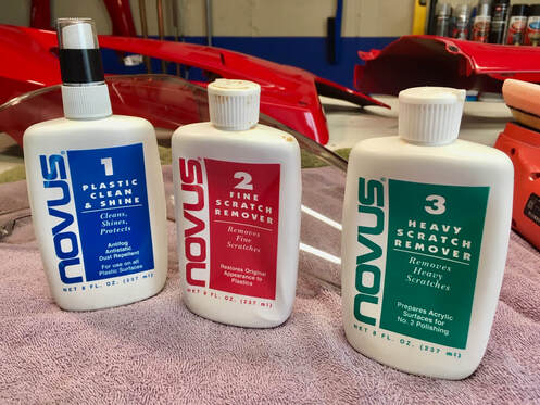
Time and neglect will often leave our acrylic windscreens in need of some TLC. Here's how I help out a weathered screen.
I've used Novus plastic polishing products for many years, but I've also found that going through a refinishing process just like I use on painted surfaces works well also. Either way, we can do a lot for our windscreens with some time and effort.
I've used Novus plastic polishing products for many years, but I've also found that going through a refinishing process just like I use on painted surfaces works well also. Either way, we can do a lot for our windscreens with some time and effort.
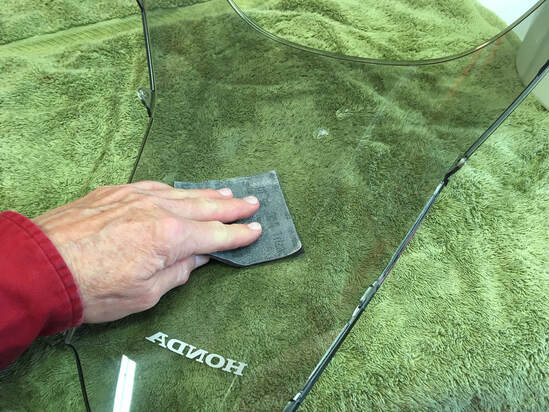
Bug juice left on for the long-term will actually imprint itself in paint and plastic. To help with the initial cleaning, I first soak the screen overnight with a wet towel draped over the screen followed by a good scrubbing with a bug sponge.
I begin the polishing process the same as with a painted surface — a light sanding with a 5000-grit wet/dry sponge. Windscreens often have a coating of some sort for UV and scratch protection, so caution is called for here — only a very light sanding. I'm trying to get off scuffs, light scratches and bug marks.
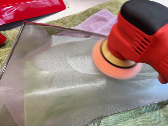
Next, I do a gentle, low-speed machine buffing with Meguiars #83 compound (or Novus #3), followed by a wipe and a second buffing with Meguiars Ultimate Compound (or Novus #2)..
I refinish one side of the screen completely before beginning the other. This allows me to gauge my progress through the clear plastic.
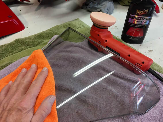
A final wipe with a clean microfiber cloth, then an application of Meguiars Polish (or Novus #1, Plastic Clean & Shine), to give gloss and protection. A quality car wax works well also.
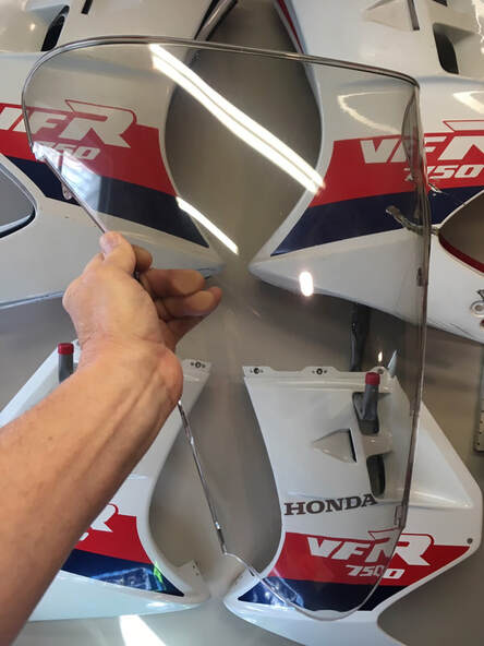
The finished product. We can't do much for deep scratches, crazing or UV damage, but an otherwise serviceable windscreen can be given a second chance.
A word on plastics care. In my aviation days, I learned that the only things that should touch acrylics are water, your clean hands and microfiber cloth. Aircraft windscreens and windows are acrylic...expensive acrylic. The love you give them reflects in your pocketbook (and flight safety).
The safe way to clean acrylic is to flow clear, clean water over the screen while gently rubbing with the palm of your hand (no rings!) till the dirt and bugs dissolve. A diluted gentle soap can be used if necessary. Then dry with a known clean microfiber towel. If a drying towel is contaminated with any kind of grit it can't be used again till it's run through a washing machine (speaking of machine washing, never use fabric softener or dryer sheets when washing microfiber). The time to clean windscreens is right after riding when the bugs are still soft. If you find yourself with dried bugs, pre-soften them with a spray of hydrogen peroxide, allowing them to soften a few minutes before washing.
I always pack a microfiber cloth when on a ride for my face shield and windscreen. I also pack a small, clean water-soaked cloth or microfiber sponge in a ziplock baggie for washing the shields, which goes into the wash after the ride. NEVER use gas station water, scrub brushes, or paper towel to clean acrylics!! You're doing more harm than good.
Plastics are one place where taking a long-term view pays off.
30. Electrical Relay Installation
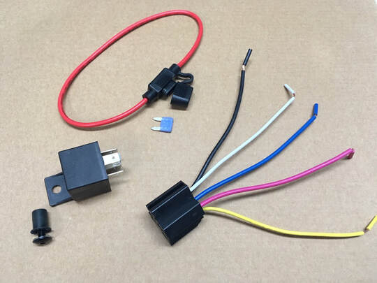
I often find the need to supply power for additional electrical accessories, typically heated hand grips and GPS/phone power. That process begins with supplying 12 volts of power to the front of the bike. A quick and easy solution might be to simply tap into a handy wire that has keyed power, like one of the running lights. But for things that draw substantial amps I want full power available. Another consideration for using a relay might be that an owner may want to add additional power accessories, like a power socket or heated gear connection. And that's why I like to install a keyed relay. I know that a full-amp power source is at hand.
I begin with the items shown at right, sourced from eBay, Amazon or a local parts store. Here, I'm using a five-wire relay (a 4-wire is fine also) plus a fused power wire (the red loop thingy). I will use a five- to ten-amp mini fuse.
The wires are used as follows:
Black: 12v power direct from the battery.
White: Ground.
Pink: Power "out."
Yellow: "Trigger" power (activates the relay).
Blue: This wire has an opposite function; it is only "live" (closed circuit) when the key is off. That way power can actually be fed back into the battery. With the key on, it's open, or "dead." That makes it a perfect splice for a battery tender, as it will only work with the key off. A four-wire relay omits this wire.
(Below) Next I'll need a spot to mount the relay. The VFR800 has a few choices; some bikes don't. I find a nice spot near the rear brake fluid reservoir, mark the mounting hole, drill, and insert a well nut. In this case, I can't access the underside, otherwise I could simply use a nut and bolt to secure.
(Below) I want to use that reservoir mounting bolt as my ground, so I remove it and grind away any paint, giving a clean, effective electrical ground.
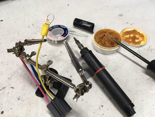
Time to make some connections. Crimp connectors have their place, but I sure feel better when there's some solder involved.
I use my Weller Portasol, a butane powered iron — no wires! I'm also a believer in flux, even though it's old school and not technically necessary with flux core solder.
(Below) I make all the wire connections to the harness and then extend them out to their respective destinations, beginning with the ground, 'cause it's closest (left photo). Then the fused power lead from the battery positive. Next, I'll select a "trigger" source — this activates the relay when the key is turned on, so any convenient keyed wire will do. I this case I chose the license light wire and use an easy side-by-side connector (left photo). I will later securely tape this connection. Lastly, the power "out" wire is extended toward the front of the bike and the work under the seat is complete.
(Below) With all the wiring secured, I run the (blue) power wire forward along a convenient path, keeping clear of hot parts or anything that could cause chafing. In this case I followed the brake lines along the top of the left-side frame. Once I exit into the headlight fairing, I test that power is indeed supplied when the key is turned on, and this relay installation is complete.
Next, install and wire a set of heated grips — next post.
Next, install and wire a set of heated grips — next post.
31. Heated Grips Installation
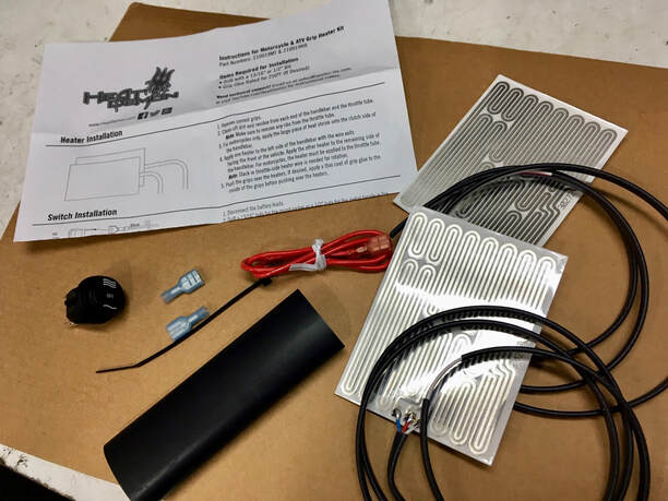
Year's ago I discovered the convenience of heated hand grips on motorcycles, and all my bikes are so equipped. Unlike today, vintage bikes didn't have the factory option, so I install my own. Here, I'll be using an "under the grip" aftermarket kit from Heat Demons by Symtec. I've used these for years with good results. I find them online for about $50.
I like this type of installation because it allows me to use whatever handgrip I choose, even the OEM replacements, which are still available from Honda. I've used other style kits, like Oxford, and I've found that they're capable of greater heat output, but this kit supplies all the heat I've ever found necessary and is less expensive. The kit contains everything pictured, including your choice of a toggle or rocker switch. I've chosen the rocker. These kits are available with a handy switch mounting bracket which allows mounting on any 6mm bolt or screw, but this kit didn't include it. I want to mount the switch on the clutch perch, so I'll need to make my own.
In a previous post I ran a 12-volt supply wire to the headlight fairing area (see tutorial #30 "Electrical Relay Installation"). The sequence I follow is to install the heaters, install the grips, install the switch and connect the wiring. After testing, I safely tuck everything away.
(Below) These grips have seen their day, so a razor makes removal easy. I seldom reuse old grips as there's such a great variety of aftermarket available for reasonable prices. If I do want to save the grips, I slide a long skinny screwdriver blade under the grips to loosen them, squirt some WD-40 in the gap and work them off. Next, I remove any residual grip glue — we need a clean surface to adhere the heating element. Wiping with acetone or similar works well.
(Below left) Install the heating element so that the wires exit at about 1 o'clock (throttle) and 11 o'clock (clutch). Be precise, you only get one chance.
(Below right) The clutch side is provided with a length of heat shrink — it provides insulation from the metal handlebar and the heating element is installed over it.
(Below right) The clutch side is provided with a length of heat shrink — it provides insulation from the metal handlebar and the heating element is installed over it.
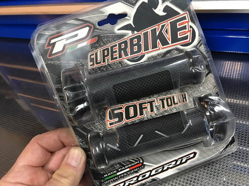
I've chosen a set of ProGrip 717 grips.
(Below) My next step is to mount the switch. If you don't mind drilling a hole into fairing panels, that would be a quick and easy solution. But I don't want to do that to these old machines, and I assume that a future owner wouldn't appreciate it either.
I like the switch near the clutch, and there's usually just enough room off the lower clutch mounting bolt. I start with a piece of flat aluminum plate and basically copy the factory bracket which I've used in the past. Here, I'm test fitting the rough bracket before final finishing and paint.
(Below left) Next, I make all the wire connections and test. Note the ground wire located to a handy frame bolt.
(Below right) After testing, all the wires are tidied up. The three wires running up to the switch are wrapped in electrical tape and tie-wrapped along the left switchgear wire loom. I like to encase the wire bundle in a length of heat shrink (arrow).
(Below right) After testing, all the wires are tidied up. The three wires running up to the switch are wrapped in electrical tape and tie-wrapped along the left switchgear wire loom. I like to encase the wire bundle in a length of heat shrink (arrow).
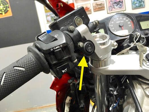
With everything in place, the switch bracket is mounted...and the project is complete.
This modern convenience added to an old bike is a practical addition, but is completely removable if a future owner desires.
This modern convenience added to an old bike is a practical addition, but is completely removable if a future owner desires.
32. Priming Carbs, Testing A Fuel Pump, Draining A Fuel Tank
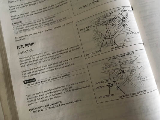
Here's a tip taken from the Factory Service Manual which allows you to accomplish three tasks with one trick.
The FSM lists this under testing a fuel pump, but I use it for all three of the above. It's basically bypassing the fuel pump relay in order to force the fuel pump to operate. The job of the relay is to allow the pump to operate only if the engine is turning over — in case of an accident slashing a fuel line, the pump won't keep spewing fuel just because the key is still on. So if we need the pump to operate without the engine running we simply bypass the relay by jumping the two contacts in the connector.
The FSM lists this under testing a fuel pump, but I use it for all three of the above. It's basically bypassing the fuel pump relay in order to force the fuel pump to operate. The job of the relay is to allow the pump to operate only if the engine is turning over — in case of an accident slashing a fuel line, the pump won't keep spewing fuel just because the key is still on. So if we need the pump to operate without the engine running we simply bypass the relay by jumping the two contacts in the connector.
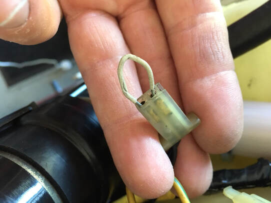
Pull the connector, insert a jumper wire between the contacts (black and black/blue in the case of the '86-87) and turn on the key. The pump will then operate, allowing you to test the pump, or test that the petcock's main and reserve are functioning, or drain the tank, or prime the carbs if they've been drained. Here's my jumper in place....
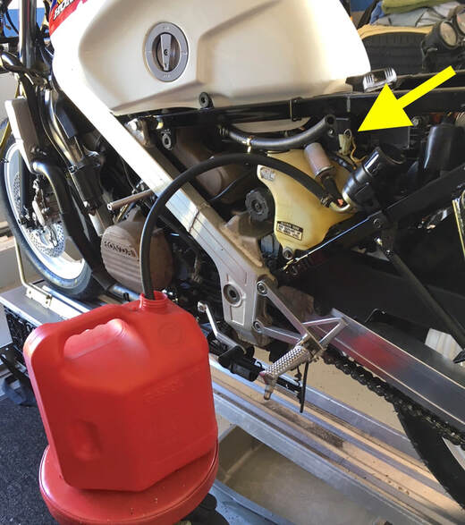
And here's what it looks like when I'm draining the tank or, in this case, testing the plumbing after installing the tank. The arrow is pointing to the jumper wire inserted in the relay's connector. Note that I'm using a spare length of fuel line to the gas can — this allows the installed line to the carbs to remain in place (and that gas can should be on the concrete floor to avoid a discharge of static electricity).
Next, I'll reconnect the line to the carbs and prime (fill) the carbs with fuel — the pump will slow to a stop when the carb bowls are full. If you skip the priming step, they'll need to fill while you crank and crank the starter. Priming is a better idea.
Next, I'll reconnect the line to the carbs and prime (fill) the carbs with fuel — the pump will slow to a stop when the carb bowls are full. If you skip the priming step, they'll need to fill while you crank and crank the starter. Priming is a better idea.
33. Trimming Or Eliminating Passenger Peg Brackets
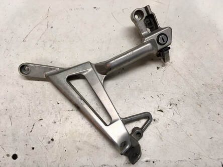
On a few of my projects I've eliminated the passenger footpeg brackets. This was done for two reasons; I didn't expect to be carrying a passenger, and aesthetics — the large cast aluminum rear peg brackets on the 3rd- through 6th-gen bikes give the rear end a visually heavy and unnecessarily cluttered look, at least to my eye. Here's how I approach the operation.
The right side bracket is also used as a muffler mount (3rd - 5th-gen), so if that's to be retained, then the footpeg mounting boss will need to be cut off and smoothed, similar to what's described below. If the muffler mounting point is not to be used, as is the case with a high-mount aftermarket muffler, the right side assembly can simply be unbolted from the subframe.
(Right) The left side, however, also serves as the handhold for raising the bike on its center stand and locates the seat/helmet lock. To keep the functionality of the handle and lock, I locate a used bracket on eBay and cut off the lower portion, eliminating the footpeg but preserving the handle and lock. By sourcing a used bracket, I'm able to provide the next owner both original brackets in case he/she would like to revert to stock.
(Below) But first, I will need to remove the lockset. These locksets use tamper-proof threaded studs which are attached from the backside. To remove them, I cut a straight groove into the bolt head, then unscrew with a straight-blade screwdriver. I then mark a cut line, and, using a larger cutoff tool, carefully make the cuts.
(Below) Another 20 minutes of grinding, filing, sanding and polishing results in a smooth factory-like handle and lock.
(Below) And here's a look at a 3rd-gen with the same operation. The left-side handle is just visible under the cowling (in this case, the lockset was discarded), while the right side still functions as a muffler mount but with the footpeg and its mounting boss removed.
(Below) And here's a 6th-gen with both brackets removed. These don't serve any additional purpose so they can simply be unbolted and the empty bolt holes plugged with some hardware store black plastic caps.
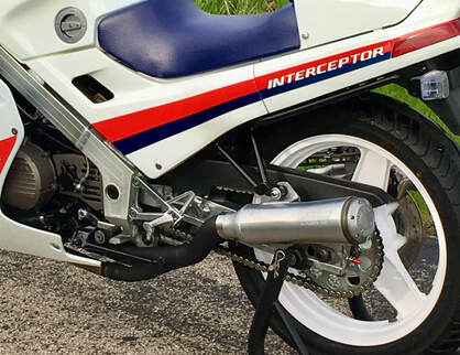
(Right) I've also eliminated the passenger pegs on this 2d-gen project. The pegs' frame brackets are welded in place on this model, so this modification is not reversible, requiring a replacement of the entire subframe assembly to return to stock. My goal here was to visually clean up the muffler mounting area.
34. DIY Gaskets
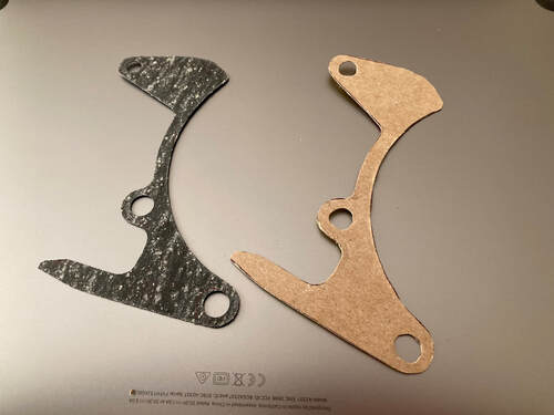
As our bikes age, OEM replacement parts inevitably disappear from Honda inventories, forever joining the ranks of "NLA" — No Longer Available. The aftermarket can help in many cases, but some obscure items just won't warrant the effort.
Case in point; paper gaskets. When I went to stock up on the gasket pictured here, I found them NLA. Fortunately, I had one left in my parts stash which gave me a perfect template for a do-it-yourself replacement project.
You can order inexpensive gasket material on the internet, and that would be advisable for fuel, liquid and any type of "pressure" application, like an engine cover, carburetor sealing or cooling system use. But in the case of less critical uses, like this 2d-gen sprocket cover gasket, any heavy paper will do just fine. In this case I used a discarded cookie box. The process is the same with sheet gasket material.
I begin by tracing the shape, then cut out each gasket with scissors or a sharp blade. The holes are formed with a paper punch. In 20 minutes I had four new gaskets to add to the parts stash. Simple, quick and cheap.
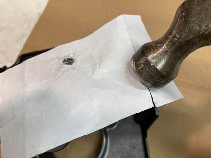
If you don't have a new or used OEM gasket available to use as a template, no worries, you can sometimes just trace the part itself or use the old mechanics' trick of "tapping out" a DIY gasket. For a quick demonstration I took a sheet of paper and tapped along the edge of this sprocket cover — you can see the nice, sharp line it creates (a lighter hammer should be used).
Below is a great video from Delboy's Garage "Simple Skills" series giving an in-depth tutorial on this technique along with a primer on the use of gasket cement. Personally, I rarely find the need for gasket cement when using OEM or aftermarket gaskets, but it will provide peace of mind when sealing critical or problematic areas.
Below is a great video from Delboy's Garage "Simple Skills" series giving an in-depth tutorial on this technique along with a primer on the use of gasket cement. Personally, I rarely find the need for gasket cement when using OEM or aftermarket gaskets, but it will provide peace of mind when sealing critical or problematic areas.
35. Modify Fenders, Front & Rear — 2d-Gen
Changing the shape of your front and/or rear fenders can freshen the look of the 1986-87 VFR. The rear is a common mod, eliminating the bulk of the license plate light and lower reflector. As for the front, the original fender has a "heavy" look which was changed in the later generations to a much sleeker and visually lighter style. This is also an effective fix for a damaged front fender. All that's involved is a willingness to work with plastic…and you'll need to repaint the front fender. Let's begin with the rear.
————————--
Reader Scott sent along some photos of his very clean rear fender bob on his VFR700 F2. The 2d-gen's fender is a separate extension piece which bolts to the main fender structure, while the later bikes were a single unit. This allows a complete removal of the extension and bolting on an aftermarket metal license bracket. Another approach is to shorten the existing fender, eliminating the bottom reflector and even the bulky license plate light, if desired. This is the route Scott took and he did a smooth job of it.
Remember, most, if not all, states require a rear reflector and license plate light, so proceed accordingly.
Scott solved the lighting question by wiring in LED lighted license bolts. Another option is to source a stick-on LED light and mount it to the bottom of the tail light. He traced out the side curve using an 18-inch wheel rim, then ground the shape with a bench grinder stone, though any method can be used to cut the plastic to shape, then smoothed. The side of the stone produced a straight lower edge, but a long file can also be used, or sandpaper wrapped on a length of flat board. He then finished up with sandpaper to smooth and round the edges. Comparing Scott's to the OEM fender in the photos below, you can quickly see how the modification visually lightens the rear of the bike and yet retains the original style line.
(click on an image to enlarge)
My Front Modification
The two photos below show the difference between an OEM and my modified front fender. My goal was to visually "lighten" the front wheel area, which I think melds better with the rest of the bike's lines. Additionally, I eliminate the squared-off front and rear of the fender, which give a much more modern look. The later generation bikes incorporated similar changes, but this is strictly a personal preference.
The two photos below show the difference between an OEM and my modified front fender. My goal was to visually "lighten" the front wheel area, which I think melds better with the rest of the bike's lines. Additionally, I eliminate the squared-off front and rear of the fender, which give a much more modern look. The later generation bikes incorporated similar changes, but this is strictly a personal preference.
I begin with a template, which is the cut-off portion of an earlier fender I modified. After tracing a cut line, I carefully make successively deeper cuts with a dremel tool, leaving a rough edge.
If I wish to sharpen the nose and tail portions, I trace a shape on stiff paper, cut it out and transfer to my fender (this shape was taken from a Magna front fender I happened to have in the shop). With a combination of files and successive grades of sandpaper I shape and smooth the edges. In this case, I chemically stripped the rattle can blue paint, followed by a final prep sanding with 320-grit wet/dry sandpaper. Ready for paint.
36 • Clutch Slave Cylinder Overhaul
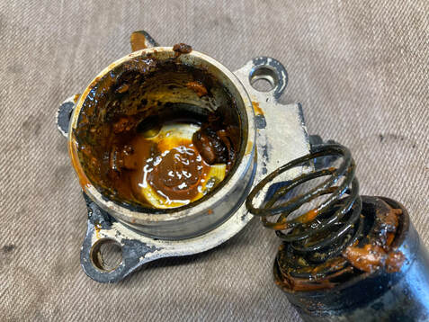
Hydraulic brake components don't fare well when neglected, which is why manufacturers specify a 2- to 3-year fluid replacement. Unfortunately, "out of sight, out of mind" often prevails so the clutch slave pictured here is more typical of what I encounter in my projects. Let's try to save this assembly, which will apply to all VFR slave cylinders.
It's a simple mechanism, a large piston is pushed outward in its bore by hydraulic pressure from the master cylinder, moving the clutch rod which passes through the crankcase to the clutch basket, separating the clutch plates, which achieves a disconnect between the engine and transmission. Hydraulic pressure is held captive by a single large seal on the piston. All we need to do is clean everything, smooth the piston and bore and fit the fresh rubber seals.
(Below) After cleaning with soap & water, I inspect the bore for deep gouges or corrosion, which would prevent sealing, but this one looks useable — the arrow shows the area where the seal actually moves, so that's the critical point in the bore. I begin with a brass rotary brush to remove staining or deposits missed by cleaning and then move on to finger sanding with wet/dry sandpaper, the grit depending upon the condition of the bore and piston. Here. I'm finishing up with 1000-grit.
(click on an image to enlarge)
Ready for assembly.
(Below) After lubricating with brake fluid, I install the main seal being sure that the larger lip faces the spring. Next, the clutch rod seal is pushed into place with the flat side facing outward. Then coat the bore with brake fluid.
(Below) Carefully align the piston and bore so that with firm, even pressure the piston slides home. When installing onto the bike, refit the bleeder valve, add a dab of grease into the rod's cavity and fit a new gasket (available from Honda). This job is complete, and, with regular fluid changes should be good for a few more decades of use.
37 • Refurbishing Exhaust Pipes
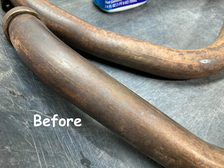
Checking out YouTube on this subject will show several videos on the use of a UK product called Harpic, a caustic toilet bowl cleaner. The edited videos make it look effortless, so I grabbed our Walmart bowl cleaner along with some Lime-A-Way and Rustoleum gel rust remover. I also gathered four grades of scuff pads and set to work in a home-brewed comparison.
As it turns out, Harpic is 10% hydrochloric acid and mine uses sodium hypochlorite which is likely lacking the same etching power. In any event, as I progressed through the products, I was slowly getting results but doing a lot of scrubbing. So I decided to try some light grade sandpaper — 1200-grit wet/dry. Things went much quicker but I eventually realized that sandpaper and water alone achieved the same results just as quickly as any of my products. In particular, the rust remover didn't seem to do a thing, which tells me that the discoloration isn't a rust issue.
As it turns out, Harpic is 10% hydrochloric acid and mine uses sodium hypochlorite which is likely lacking the same etching power. In any event, as I progressed through the products, I was slowly getting results but doing a lot of scrubbing. So I decided to try some light grade sandpaper — 1200-grit wet/dry. Things went much quicker but I eventually realized that sandpaper and water alone achieved the same results just as quickly as any of my products. In particular, the rust remover didn't seem to do a thing, which tells me that the discoloration isn't a rust issue.
(Below) Once the corrosion is dealt with I'll want to bring out the shine by buffing with a metal polish, in this case Autosol, an excellent general purpose polish. I begin with a once-over by hand (look at that black residue!) then a final machine buff.
This is a labor intensive process. but the results are pretty amazing. I should note that my intent here is not to have chrome-like exhaust pipes on my street VFR, but rather to achieve a factory-like fresh start for these pipes. The pipes will slowly take on a satisfying bronze color with use, which I think is very attractive. I think a simple hand polishing every few years will keep these looking great.
This is a labor intensive process. but the results are pretty amazing. I should note that my intent here is not to have chrome-like exhaust pipes on my street VFR, but rather to achieve a factory-like fresh start for these pipes. The pipes will slowly take on a satisfying bronze color with use, which I think is very attractive. I think a simple hand polishing every few years will keep these looking great.
38 • Installing Windscreen Molding — 2d-Gen

Like owners manuals and tool kits, Gen-2 windshield edge moldings seem to have a mystifying habit of vanishing over years of ownership. Nearly all my 1986-87 VFRs have come to me with the soft plastic edging missing in action.
The molding has been NLA from Honda for several years, but some time ago I found three OEM sets available on eBay and grabbed all three, one of which came in handy as I put the final touches on this project. For a substitute part, see the notes below.
To my surprise, I didn't have any end clips in my parts stash, but, equally surprising…Honda still does. My local dealer had them ready for me five days after ordering: $5.20 each. The molding is very soft and flexible — very much like silicone — and has extra length, as it's used on other Honda models. Here's how I install the molding.
(see photos below, click on an image to enlarge)
The end clips have an open end and a crimped, or closed end. The crimped end is first installed onto one end of the molding, and I then use a small screwdriver to seat the molding fully into the clip, also spreading the clip a bit to aid in pressing it into place onto the windscreen (if reusing an old clip, you needn't spread it). I install the first few inches of molding onto the screen and press the clip into place. Note that you will be pushing and pressing forcefully as the screen/fairing creaks in protest, so support the screen as you proceed.
I wet the screen edge with a water-soaked towel to help the molding slip into place (alternatively, heat gently with a heat gun), then work my way along the screen edge. Be certain you're fully seating the molding, as it affects the final length. Nearing the end, I mark the end point and cut the excess. Install the clip onto the molding, seat and spread the clip with the screwdriver, and press into place. Finished.
NOTES:
• Reader Kevin shared that he has found a substitute molding from Suzuki; part # 94631-33C01, about $16
• No glue is required to install the molding.
• If you're reinstalling an old molding which has stiffened with age, try softening with a heat gun or soaking in hot water, pressing into place while warm.
39 • Chain & Sprockets Installation

This is how I fit new chain and sprockets on my projects. In this case I'm installing on a Gen-2 VFR, but it applies to most installations.
Here, I've chosen JT brand steel sprockets in stock sizes (16/45 tooth), and a Bikemaster X-ring chain in nickel finish. I also opted for a rubber-damped front sprocket, just because.
(Right) I'm guiding the new chain around the front sprocket — it's not obvious, but the rear tire is clear of the lift so that the wheel rotates as I guide the chain through the frame and over the sprocket. Notice the notes on the frame and rear sprocket to remind me to torque the fasteners once the chain is installed and the tire lowered.
(Below) I'm using my trusty Motion Pro chain breaker/riveting kit. Chains are often packaged with the correct number of links, but this one came with about five extra links, which I marked and drove out the necessary rivet. Here, you can see the driven rivet and its o-rings. The new master link is greased and ready to install. This is a rivet-style master link, the "clip" style is not appropriate for high performance street bikes.
(Below) Next, I install the new master and o-rings from the backside. The front plate then needs to be "pressed" to achieve the correct width. Be sure to keep the rivets centered in the tool's holes, so as not to inadvertently mushroom the rivet (pink arrow). As I'm pressing the plates, I pause to check the width, matching it to its neighbors.
(Below) With the correct width, I reconfigure the tool to rivet, basically mushrooming the soft rivet to lock the plate in place (no photo). The rivet needs to be just right, too tight and the link won't want to pivot as the chain wraps around the sprockets, too loose and you risk the plate coming off — you can imagine the result. Here, I'm measuring the pressed rivet's diameter — the chain manufacturer will provide a recommended diameter range; 5.48mm is perfect. This is what your finished rivets should look like.
(Below) Finally, with the sprockets now held firmly in place by the chain, I'm able to torque the sprocket fasteners. At the rear, I've numbered the nuts to help me torque them in a crosswise pattern (you have to raise/rotate the wheel to access each nut, and you can easily loose track). After torquing the front bolt, I add a line of white paint. This allows a quick inspection through the sprocket cover to verify that the bolt hasn't loosened.
Rear nuts: 58-72 ft-lb
Front bolt: 38 ft-lb
After adjusting the chain tension, this job is finished
Rear nuts: 58-72 ft-lb
Front bolt: 38 ft-lb
After adjusting the chain tension, this job is finished
