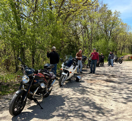
Honda's V4 Interceptors
V4 Dreams
  • Home
  • Shop Blog
  • Maintenance
  • Products
  • My VFRs
  • Historical

Thank You, Mr. Barber

2/20/2026

0 Comments

 
George W. Barber 1940-2026
PictureClick on image for George's obituary
Motorcyclists, and the world in general, lost a friend, visionary and generous benefactor this past week.

Best known to most of us as the founder and inspiration for Barber Vintage Motorsports Museum, George's influence actually spread far and wide throughout Alabama and the southeast U.S., funding hundreds of scholarships, promoting conservation and benefiting the lives of countless people and organizations, all with consummate humility and compassion. He will be missed on a personal and professional level but his work will live on for generations. Click on the image above for his impressive life story. Well done, George, rest in peace.

Picture
The Barber Motorsports complex is a bucket list item for any serious motorcyclist

In the fall of 2007, I took a memorable 4000-mile tour to the 2d-annual Barber Vintage Festival near Birmingham, Alabama. I had Project #1 in the garage but for this ride I chose the Suzuki V-Strom 1000. My route began in Madison, WI, traced northeast along the Ohio River, breaking east at Parkersburg, WV where I worked my way through the Shenandoah Valley to Waynesboro, VA and milepost 0 of the Blue Ridge Parkway. I rode in the autumn tranquility for the Parkway's full 469 miles to Great Smoky Mountains National Park, then the many famous and infamous roads of the southern Blue Ridge, Including my first sampling of the Dragon and Cherohala. Right on schedule, I rolled into the Barber complex for the beginning of the festival, including leisurely tours of the awesome museum.

​(Below) The museum offered this very cool Interceptor exhibit, displaying the VF1000R, VFR750F and VF500F. If you click on the image of the display plaque you'll see in the lower right corner "BMC-002," which indicates that the VFR was the second bike George acquired for his collection, the bike's odometer showing .9 miles. I don't have a photo, but I think that the VF1000R was BMC-001. He obviously thought highly of the V4s.
0 Comments

Vegas 2026 - V4 Auction Results

2/17/2026

0 Comments

 
The annual kickoff to the motorcycle auction season was held in Las Vegas, January 26-30. Mecum Auctions (sign-in required to view results) is considered the benchmark player in this arena so I went through the results for Honda V4s and came up with the following nine sales. Unfortunately, Mecum provides minimal details for the bikes so any value generalizations are just that, generalizations. But, a cursory look at selling prices seem to show values continuing to dip. In no particular order….
Picture
$7150 - 1985 VF1000R

Showing only 6488 miles, this square headlight example presents beautifully. From the Mitzel collection, it's likely original condition but does have an aftermarket muffler.

In recent years, nice "R" models typically fetched $10,000 all day long so this seems like a relative bargain. 


Picture
$5500 - 1984 VF1000F

A second 1000 offered by Lee Mitzel, this "F" model also presents beautifully and shows 10,600 miles. This is either an exceptionally well-preserved survivor or a full restoration; it's that nice.

I have a soft spot for the "F" version but even so, this selling price seems more than fair.


Picture
$5225 - 1985 VF700F

Also from the Mitzel collection, this pristine final-year tariff-buster VF700 shows only 6281 miles. Probably my favorite of this year's V4 sales, this thing is just stunning up close. While the 750 version may be preferable, I would be proud to have this in my stable, and excited for every Sunday morning ride.

The values for the VF700/750 series are all over the board, but, again, this seems very well bought.


Picture
$1375 - 1985 V65 Sabre

The bargain of the V4 sales, this big-block VF1100S Sabre shows 23,393 miles and lists as "highly original stock condition." These were 122 HP tire-smokin' street bruisers in their day, shaft drive and all. This one looks like a nice rider-grade example with good paint — even the impossible-to-find black chrome mufflers look to be in great shape. Again, well bought.


Picture
$6600 - 1987 VFR400R NC24

The VFR400 models were well-represented this year including this 2d-gen NC24 version. With 23,888 kilometers this has a rider-grade patina and sports later model wheels.

NC24 values depend largely on condition, and this one seems to fall mid-range.


Picture
$4950 - 1987 VFR400R NC21

Also an '87 model, but this example is the final year of the Gen-1 NC21. This example is from the David Silvers collection and shows 20,040 kilometers. Looking very much like a scaled-down VFR750 this one is a little rough around the edges, which the selling price reflects.


Picture
$2200 - 1986 VFR400R NC21

Also from David Silver, this represents the first year of the revamped 400 V4s, replacing the VF400F. Showing 27,835 kilometers this example is cosmetically rough, even dirty, and the selling price seems right in line with the condition.


Picture
$5500 - 1992 VFR400R NC30

Also from David Silver, this striking example, at 35,514 kilometers, showcases the final model and year of the VFR400R, and definitely the pinnacle of the series. The cosmetics and mechanicals were based heavily on the larger RC30, the little engine now revving to 14,500 RPM and rated at 65 HP (!). Two color schemes were offered in the UK, but I'm not sure this was one of them.

0 Comments

NOS Fuel Tank: VF1000F

2/11/2026

0 Comments

 
PictureClick on image for the FB M'place ad
Here's something just about as rare as 30 days in February; a new-old-stock fuel tank for a 42-year old Honda V4.

This beauty is for the one-year only 1984 VF1000F. The seller notes, "...in original Honda plastic bag. Totally new. Mint." The listed price is $1500 and located in my hometown; Madison, WI. The seller is a long-established speed shop; Motorcycle Performance, a cool place with a well-earned reputation for competence and integrity; buy with confidence.

I had a NOS Gen-2 r/w/b tank that I hoarded for several years awaiting the perfect project. I put its value at $1200, so I don't consider this price out of line — after all, they're not making any more.


0 Comments

Got An Extra One-third Million $$?

2/9/2026

0 Comments

 
PictureClick on image for the Iconic link
What: 2016 RC213V-S
Why: Honda's pinnacle sport bike
Where: Dublin, Ireland
Price: Reserve auction ends Feb. 14
UPDATE: No sale: bid to $250,000, reserve not met.

Back in 1992 Honda offered the most expensive production motorcycle available, the NR 750, priced at a cool $50,000. Fast forward to 2015 when Honda announced their new MotoGP contender, the RC213V (spoken R-C-twenty one-3-V), a 1000cc V4 with the potential to produce something over 200 HP in factory race tune. If you qualified for the exclusive buyers' list it would have cost you $184,000 in 2016, which converts to about $247,000 in today's U.S. dollars. Honda also offered a Sports Kit (-S option) which added several go-fast parts and an additional $12,000-$15,000. Auction sales of this model have exceeded $300,000. The factory planned to build 250 street bikes but the Fukushima tsunami cut that to about 125 actually produced that first year at the rate of one per day with as many as 300 eventually built.

This example, available through Iconic Motorbikes Auctions and located in Dublin, Ireland, is a collectors example of the highest order, even including the Sports Kit. The seller is the original owner, stating;  “When I got it I had to ride it just to experience the best motorcycle ever built. I rode it on quiet country roads on the outskirts of the city, then stored it in a temperature controlled garage with a few other iconic motorcycles.” Thus, the 33 miles showing on the odometer and in "immaculate condition." 

The RC213V remains Honda's MotoGP weapon, though with major changes, particularly in 2022. An upcoming rules change for the 2027 season will likely mean the end of the line for the model.

What's your guess for the final selling price, assuming it meets the seller's reserve?

(thanks to Bazza for the listing heads up)

Honda's 2026 season RC213V-S MotoGP contender, pictured with factory rider Joan Mir.
Picture
0 Comments

RC30 eBay Auction

2/7/2026

0 Comments

 
PictureClick on image for the eBay link
What: 1989 VFR750R RC30
Why: Near perfect, low miles
​Where: Seattle, Washington area
Price: Auction ends Feb. 9
UPDATE: No sale; bid to $37,100 reserve not met.

This is the second RC30 I've featured in the past week. ​This one is selling on a reserve auction, currently at $25,100 with reserve not met.

This is a Canadian import (the U.S. got the RC30 in 1990 only) and shows just 1911 miles, the VIN indicating it was number seven off the line in 1989. The seller states that he's had it in his collection for 18 years and brought it to riding condition in 2024, adding that it's "all original paint…no accidents." Included are the Honda rear stand, tool kit, owners manual, keys and a clean US title.

The photos show a near perfect survivor of one of the most collectible modern production motorcycles. It will be interesting to see how the collector market values this in 2026.

0 Comments

Tool Time: Using Torque Wrench Adapters

2/6/2026

0 Comments

 
Picture
This morning the Rock Auto monthly digital newsletter arrived in my inbox (a short but entertaining newsletter, BTW), and a feature dealing with torque wrench extensions caught my eye.

The issue discussed is that when your torque wrench can't reach or needs an adapter for a specific fastener, you may need to adjust the torque setting to compensate…if the adapter effectively lengthens the tool. However, if you can use the adapter at 90°, the torque remains unaffected. From the article:
"The torque setting on a torque wrench is based on the distance from the socket to a spot on the handle. If an adapter is put on so it lengthens the torque wrench (parallel with the torque wrench) then the tool becomes a longer lever that applies more torque than the setting on the wrench. For example, the torque wrench may be set to 30 ft-lbs but the crows foot sticking straight out the end of the wrench (see above illustration) may actually be applying closer to 35 ft/bs.

To avoid applying more torque than the wrench setting, put the crow foot on so it is perpendicular (90°) to the torque wrench. This will avoid changing the overall length of the torque wrench and maintain the accuracy of the torque setting."


However, the 90° tip isn't always possible. If not, here's a formula to help figure the compensated torque setting, shown below. As an example, if our normal length of the torque wrench (L1) is 15" (measured from the center point of your hand placement) and our extended length with the adapter (L2) is 20", we divide 15 by 20, giving .75. Then multiply our torque spec (M2), let's say 30 ft/lbs, by .75, resulting in our amended torque setting of 22.5 ft/lbs (M1), resulting in 30 ft/lbs at the fastener.

I don't often have the occasion to use adaptors, but this is the correct way to compensate if needed.

Picture
Speaking of adapters, here's a couple of examples I found on Amazon; click on the images for links.
0 Comments

RC30 Back On The Market

2/5/2026

0 Comments

 
PictureClick on image for the RSBFS link
I featured this 1990 U.S.-spec VFR750R in last month's Shop Blog when it was up for eBay auction, failing to meet reserve.

It's now offered as a featured listing with Rare Sport Bikes For Sale (.com). The ad copy appears to be taken from the eBay listing, so no new information that I noticed to be had there. Interestingly, there's no sale price provided, just a phone number. Ebay bidding ended at $59,600 so the asking will likely be north of that. Click on the image or visit my previous posting for a little more information.

0 Comments

Carb Rescue, Part 3 — Assembly

1/30/2026

0 Comments

 
This is the final tutorial in my carb rebuilding series; Parts one & two can be found in The Shop Blog, December, 2025. You'll also find related tutorials on the Maintenance page.
I'm using a Gen-3 carb set ('90--93), but this is generally applicable to all V4 carburetors.
​We left off with the carb set cleaned, inspected and any replacement parts on hand.
Let's get these back together….
(Below) I'll want to first install any parts which are more accessible with the carbs separated, so I begin with the air cut valve assemblies (Gen-3 and -4 only). First, I set the oval o-ring in place, flat side toward the carb body, then set the diaphragm in place, the small "needle" inserted into the carb body. I've treated the rubber with a light coating of Red Rubber Grease to soften and preserve the diaphragm. With the spring in place I press the cap straight downward, keeping the diaphragm centered, and hold it firmly while installing the first screw — a magnetized screwdriver tip really helps here. These are fiddly assemblies to install due to the firm, wobbly spring, so proceed carefully. Tighten both screws firmly and install the remaining three assemblies.
(click on images to enlarge)
(Below) Next I'll install the fuel mixture (pilot) screws and the enriching (choke) assemblies. I first assemble the mixture screw's spring, then washer, then o-ring and gently seat them fully, then back off 2 1/4 turns (2 1/2 for Gen-2) — this is a good general starting point; an additional quarter turn is a good idea for intake or exhaust modifications. For reference, turning out is more fuel, in is less. Note the black marker on the screwdriver blade; this helps me keep track of rotations.

Note the differing choke shafts and their placement. Assemble the shaft, spring and cap, installing into carbs #1 and 4, gently snugging the cap with a 14mm wrench or pliers. Installing #2 and 3 choke shafts is more involved, assuming you'd chosen to separate those carbs. This is covered in depth in a September 2025 Shop Blog post, "Separating Carburetors, The Easy Way."
(Below) I'll move on to slide/diaphragm installation next. I first need to install the plastic needle holder into the bottom of the slide (not applicable to Gen-2); this part goes in flat ears first — it's fiddly, but you'll know it's right when the tabs are flush into the bottom recesses (see last photo). I then install the jet needle, using a needle nose pliers and tilting upward to keep the washer on the needle, followed by the spring cap, snugged in place with an 8mm socket. Finally, test that the needle moves freely in & out (a few millimeters) with slight spring pressure.
Note: The Gen-4 slide design is very different, with its own assembly procedure; refer to the FSM.
(Below) Next, I'll fit the assembled slide/diaphragms into their bores. Slide an assembly into its bore, ensuring that the rubber perimeter ridge seats all the way around and the small tab is located correctly (photo 1). Also check that the jet needle has engaged its jet hole correctly (photo 2). I find that keeping the diaphragm raised and holding it with my left middle finger (photos 1 & 4) works best for the next step — insert the long spring, and push downward with the diaphragm cap to engage the cap's tiny raised dowels, all while holding the slide upward; if the cap doesn't seem to positively engage its dowels, try again till it does. It's important that the rubber diaphragm is fully seated in its groove around the perimeter. Holding the slide and cap stationary, install the four cap screws (photo 4); here I'm using an electric screwdriver which makes one-handed screwing easier. Then tighten the four screws (photo 5). Finally, test the slide action by pushing all the way upward and letting it fall on its own — there should be mild resistance going upward and a slight "whoosh" as the slide drops smoothly and gently all the way down to the closed position (photo 6). If you're not getting that action, consider rechecking the diaphragm fitment. If it feels good, proceed to the other three slide/diaphragms.
Picture
(Right) I find it easier to fit all four diaphragm caps and then go back and install any ancillary pieces, like the choke cable bracket on #4 carb, shown here. I'm more confident in having installed the diaphragms correctly when only having to deal with the bare screws and not their connecting parts. Here, I'm adding a new screw for the hold-down bracket (it was buggered up) — it's the same screw as the cap screws. Replacement screws are available on the "Products" page.

(Below) I'm now ready to install the fuel and vent lines. In the first photo, fire damage actually melted a hole in this vent tube but fortunately I had a spare on hand. If I hadn't had a spare I would have simply put two layers of heat shrink tubing over the area, as these vents will be open to the atmosphere so are not an airtight system. Next, I install fresh fuel tube o-rings and coat all the o-rings with Red Rubber Grease or similar.

I can't demonstrate the tubes' installation in photos, but after an appropriate amount of fumbling about you will eventually get all the tubes in their correct positions — you took photos, right? In any event, photo 3 below shows the correct routing (Gen-3). California-spec carbs have a slightly different-looking vent tube but it installs in the same relative position. On the Gen-3, the hose clip (photo 4) holds the fuel line from carbs #1/3.
NOTE: Gen-2: The choke rod assemblies are installed during the above exercise.
NOTE: For more reference photos of the various generations, see the Maintenance page, end of post #1.
Picture
(Right) With everything in place I like to carefully flip the carbs to the engine side and loosely install the center joining bracket which will help hold the tubes in place until I complete the next step: installing the plenum.
(Note: we need this bracket loose enough to allow the carb set to flex enough for the plenum to slip into place)

(Below) Here's some tips for preparing the metal plenum for a smooth install. In case you've lost track, on the Gen-2 and -3 this shark fin on the plenum goes between carbs #1 & 3 (photo 1).

I need to verify that all the dowel pins are in place by holding the plenum above the carbs and visually checking every hole has a corresponding pin; some will be in the carbs, some in the plenum (photo 2) — I didn't remove any dowels that were reluctant to remove as they are easily deformed if forced; just leave them in place during the rebuild process. But, to make them easier to slip into place, I clean any accumulated corrosion with a small Dremel wire brush and lubricant the dowels and their openings with a light oil (photos 3 & 4).

For carbs with funnels, like these, it may help if you set each funnel in place on the carb bodies, seeing how the tabs engage, then mark their orientation with a bit of tape or marker (photo 5), then loosely install into the plenum openings with your markers roughly oriented (photo 6). This will help with getting them lined up correctly when lowering the plenum into place.
(Below) Before lowering the plenum in place, verify that all the fuel/vent tubes and lines are still in place and that the carb-to-plenum o-rings are sitting correctly in their grooves. Then lower the plenum onto the dowels, get all four funnels into their slots (photo 1), and work the carbs as flush as possible by hand. Like fitting the fuel/vent lines, this is a juggling act but it can be done. Watch for the fuel/vent tubes to stay in place, they can slip out easily. There will likely be slight gaps between the carbs and plenum due to the tight fit of the dowels, but we'll address that as we snug the screws down.

After a few attempts, and with everything in place, install the plenum brass washers and screws, but just bottom the screws in place, don't force them down yet. When all the screws are bottomed, gently tighten them in an alternating sequence, looking to see that the carbs are gently lowering flush to the plenum — again, don't use force; if it's taking too much effort, something is out of line and causing a bind. I don't bend the washers' locking tabs at this point — I actually wait till the carbs are tested and tuned, just in case they would need to come apart; we don't want to bend those soft tangs more than necessary. NOTE: the washers are available from Honda.

With the carbs seated to the plenum, the carb set is now firmly held together. Flip it over and check that the throttle and choke linkages move freely (photos 3 & 4), if not, figure out why. Visually check that the fuel/vent tubes and lines are still in place, if not, remove the plenum and try again.

Next, I install the underside bracket (or tighten, if already in place). It is important that this bracket naturally lies flush with the carb surfaces (photo 5); we don't want to force the carbs into place with this bracket — if the bracket doesn't lie flush, something is not assembled properly. When all is right with your world, tighten the eight bracket screws (photo 6) and retest the throttle and choke linkages.

Gen-2 and -4, tighten the side screws or nuts.
(Below) Next I install the springs and choke rod assemblies. The two throttle shaft springs slip easily into place (photo 1); the larger between carbs 2 & 4, (Gen-4: between carbs 1 & 3). Next, the sync screws are inserted into the place. I try to make this easier by holding down the relevant butterfly with a finger (just enough to take up its slack) while sliding the spring into place (photo 2) — this can go smoothly or take several tries. I then tighten the sync screws (photo 3) the same amount I loosened them during disassembly, typically 4 or 5 turns (you took notes, right?).
TIP: If you have no base point for the sync screws, you can screw them in till the springs are compressed then turn out four full turns — this will give a starting point for syncing.

These Gen-3 choke rods slide through the outer carb mount, then their spring, then the choke actuating bracket and finally the second carb mount (photo 4). If a rod doesn't want to align with the two mounts, either the carbs are not aligned or the rod is bent — they must be slide freely to operate correctly. Note the correct placement of the bracket's tang on the choke plunger (circled, photo 4). Holding the choke rod in place on the outer carb's choke plunger, I tighten the bracket's screw  (photo 5). Give everything a visual inspection and, once again, test the throttle and choke linkages for proper functioning. If anything is binding, it must be addressed before continuing.
(Below) I next install the low speed and main jets. Using a properly-sized screwdriver blade, I snug the low-speed jets in place. Next is the main jet holder; I tighten the holder with a 7mm socket using only firm finger pressure on a 1/4" ratchet or wrench. Then the main jet is screwed firmly into place.
(Below) The float assemblies are next; the float holders (with washers) are firmly screwed tight with a 10mm socket, again using firm finger pressure. Drop the float valve into place and set the float in position, fitting the float's tang under the valve's wire. Slide the pivot pin into place, then check that the float bounces up & down freely. If it's binding, figure out why and fix it.
(Below) Float adjustment is a critical step. With the carb set held vertically, tilt back till the float contacts its spring and settles gently — not fully bottomed, just suspended on the spring. I set all Gen-2 and -3 at 9mm as measured from the carb deck. Here, I have my ruler marked with tape at 9mm for an easy visual picture. Adjust by bending the float's brass tang slightly up or down, as required. I use a dental pick or small straight-blade screwdriver. There's a factory tool available specifically for setting the float height, but this simple method works well for me.
(Below) With everything buttoned up in the float chamber, we can install the float bowl covers. I fit my fresh Viton bowl gaskets followed by the drain screws. I install the covers with their anti-tamper nubs (circled, photo 2) opposite of the factory position, as I've removed the anti-tamper caps from the mixture screws, rendering the whole thing moot. This will allow me to make mixture adjustments if needed, and those nubs won't interfere. Your call, of course.
NOTE: Those anti-tamper caps were EPA dictated and do not need to be installed.

I snug the screws with an electric screwdriver, with final tightening by hand. Replacement screws are available on the "Maintenance" page.
(Below) Looking over my workspace, I see only three items left. I test fit the fuel line "T" fitting and trim the lengths as desired to get a useable angle to later join with the fuel line from the pump. Slide the clamps into place, and I always add an extra at the bend point shown, but it's likely not necessary. Next is the idle speed adjuster cable. I screw it into place (note the placement of the spring and washer) and upon contacting the throttle wheel, I screw it two full turns — this gives a ballpark idle speed. Finally, the vent hose can be installed at your option. Its function is essentially to keep water out, so it could be trimmed shorter, reconnected to the emissions hardware downstream, or left off, your choice. I just trim mine below the first curve and angle it downward.
Picture
Before these carbs are mated to an engine they're leak tested. Now is the time to find and fix a leak, not after installation. With the fuel bottle filled about 2/3 to give sufficient head pressure, I leave them in the plastic tub for at least 12 hours, or even a few days.

With this final test passed, they can be drained or transferred directly onto the engine for tuning.

TIP: I actually use water for this test, which allows me to safely do this indoors. Also, if a leak is present, there's no gas to deal with while finding and fixing the leak. Just remember to drain the water from the float bowls after leak testing.


​I hope this post helps anyone in need. As always, call, text or email me with questions, comments or constructive critiques.

0 Comments

Calling All Gen-3 Carbs

1/21/2026

0 Comments

 
Picture
With my '93 VFR750 stripped and on the lift (previous post) for the purpose of some carb tuning, the next couple of months would be the perfect time to help out anyone who's thinking of having me rebuild their Gen-3 VFR carburetors, or just a simple jet clean, check & sync on a running engine.

If that might be you, contact me:
​[email protected]

0 Comments

Gaining Carburetor Access On A Gen-3

1/17/2026

0 Comments

 
In this tutorial I detail the minimum steps needed to access the carburetors when we're in the position of requiring only carburetor access. This is also the starting point when a more thorough breakdown is desired for additional service — I have a video of that process on the V4 Dreams YouTube channel. There's also a video available detailing the carb removal itself. The procedures below apply, at least in principle, to the other carburetor generations of VF/VFR. ​For further reference, the Factory Service Manual is also helpful.
The process will require removal of:

• Seat
• Side Fairings
• Tail Cowl
• Fuel Tank
​• Carburetors

(Below) After seat removal, I begin with the side fairings. Loosen or remove the four Dzus fasteners on the side fairing plus the three fasteners on the bib fairing (the bib will remain in place). The upper bib fastener is not a Dzus, bit should be some sort of annoying plastic pin. I also remove the rear screw fastener on the headlight fairing (pink arrow) to allow some movement to aid in angling the side fairing free — be very gentle separating the side/headlight fairing seam, it is stubborn and prone to cracking. Both sides need to be removed so repeat on the opposite side.
Picture
(Below) Next, I'll need the seat cowl out of the way in order to gain access to the fuel pump/filter area on the left side. Remove the four side screws and the two bolts under the seat. The cowl can be propped upward or removed completely by disconnecting the tail and turn signal wiring connectors. (Gen-2; only the fuel pump cover fairing need be removed, the seat cowl remains in place). With the fuel pump accessible, I disconnect the pump's power supply connector; this is done in order to later tune the rebuilt carb set without the fuel tank installed and I don't want the pump running dry. I then use the underseat space as a handy tool shelf. 
(click on images to enlarge)
(Below) Let's get the fuel tank off. First, remove the tank's rear hold-down nut & bolt which will allow the tank to be raised a bit to help with the following details. With the petcock "off" I disconnect the fuel line at the filter under the seat cowl — have a rag or small container ready to catch the residual fuel in the line and filter, then plug those openings. Also on the left side, I'll need to remove the frame bolt securing the fuel line — the line and bracket will stay with the tank. Lastly, unplug the fuel gauge electrical connector on the right side. The tank removes by sliding rearward, which frees the front mounts, and lifting clear.

We now have access for carburetor removal.
(Below) Carb removal has been covered here before, but here's the procedure for the Gen-3.
Remove the airbox cover screws and cover, then the base screws, remembering the hidden screw in the front. The base screws are held captive and are of a different design, see photo. In this case the two emissions hoses have been removed from this cover and plugged (circled), if not, then slide those hoses off the cover. Finally, while lifting the base, slide the oil separator hose free from the engine — no need to move the spring clip, the hose will slide off and on with the clip in place.
(Below) Remove the choke cable by loosening, but not removing, the clamp and lifting the ferrule free. Leaving the clamp in place prevents it falling into the abyss at reinstallation. Next, remove the fuel line. The line can be very stuck and the "T" fitting is plastic, so proceed gently. Try applying heat or sliding a small blade under the line (without gouging the fitting!). Resist cutting the hose with a blade, also to avoid scoring the plastic fitting. If your line looks original or just old and hardened, seriously consider replacement — it's 10mm or 5/8" fuel line (Gen-2; see Fuel Line Kit on the Products page). Cap the "T" fitting.

​Next, slide the idle adjuster free of its bracket, then remove the two screws holding the throttle cable bracket to the carbs, using the slack to remove the two cable ferrules. There's no need to touch the cables' adjustment nuts.
(Below) Specific to the Gen-3, I'll need to pivot this thermostat housing brace (pink arrow) rearward to provide access to the #3 mounting band screw. The brace is bolted to the engine (green arrow) and to the housing (yellow arrow). First I'm removing the housing screw; here, it's a 5mm allen screw, but yours might be a phillips or hexhead screw. Next, loosen, but don't remove, the 14mm bolt at the rear just enough to provide free play to move the bracket outward and pivot it to the rear, where it can remain.
(Below) Next, I can loosen the carb insulators (boots) using a long-shaft JIS screwdriver or 8mm socket. The right side carbs are accessed from the right side, the left from the left side. Loosen only the upper band screws, leave the lowers alone. You don't want to completely remove the bands' screws, so I've learned to make 25 quarter-turns on the tool. I then pry both rear carbs upward to free them, gently levering on the carb bodies, not the choke rod! Once the rears pop free, simply lift upward on the carb set (the fronts will pop free) and carefully lift away from the bike. Finally, drain the carb bowls on the bench and stuff some clean paper towel into the intakes.
Installation goes smoothly by simply reversing these steps. I'm removing these carbs in order to tune/sync a couple sets of rebuilt carbs, so while the shop is warm I install the carb sync adaptors in preparation; see tutorial #19, "Preparing For Carb Sync" on the Maintenance page.

Job done!! That's a lot of wrenching just to get at the carburetors…always makes me wish for the days working on my old BMW airhead.
0 Comments
<<Previous
Forward>>

    THE SHOP BLOG
    •••

    An on-going account of miscellaneous information, project bikes and noteworthy VFRs for sale


    Archives

    May 2026
    April 2026
    March 2026
    February 2026
    January 2026
    December 2025
    November 2025
    October 2025
    September 2025
    August 2025
    July 2025
    June 2025
    May 2025
    April 2025
    March 2025
    February 2025
    January 2025
    December 2024
    November 2024
    October 2024
    September 2024
    August 2024
    July 2024
    June 2024
    May 2024
    April 2024
    March 2024
    February 2024
    January 2024
    December 2023
    November 2023
    October 2023
    September 2023
    August 2023
    July 2023
    June 2023
    May 2023
    April 2023
    March 2023
    February 2023
    January 2023
    December 2022
    November 2022
    October 2022
    September 2022
    August 2022
    July 2022
    June 2022
    May 2022
    April 2022
    March 2022
    February 2022
    January 2022
    December 2021
    November 2021
    October 2021
    September 2021
    August 2021
    July 2021
    June 2021
    May 2021
    April 2021
    March 2021
    February 2021
    January 2021
    December 2020
    November 2020
    October 2020
    September 2020
    August 2020
    July 2020
    June 2020
    May 2020
    April 2020
    March 2020
    February 2020
    January 2020
    December 2019
    November 2019
    October 2019
    September 2019
    August 2019
    July 2019
    June 2019
    May 2019
    April 2019
    March 2019
    February 2019
    January 2019
    December 2018
    November 2018
    October 2018
    September 2018
    August 2018
    July 2018
    June 2018
    May 2018
    April 2018
    March 2018
    February 2018
    January 2018
    December 2017
    November 2017
    October 2017
    September 2017
    August 2017
    July 2017
    June 2017
    May 2017
    April 2017
    March 2017
    February 2017
    January 2017
    December 2016
    November 2016
    October 2016
    September 2016
    August 2016
    July 2016
    June 2016
    May 2016
    April 2016
    March 2016
    February 2016
    January 2016
    December 2015
    November 2015
    October 2015
    September 2015
    August 2015
    July 2015
    June 2015

    Categories

    All

    RSS Feed

Site powered by Weebly. Managed by HostGator