(click on images to enlarge)
|
|
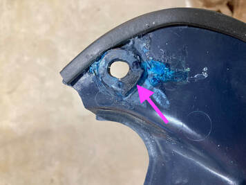
As I progress on the bodywork detailing on Project 42, a 1986 VFR750, I've come to the fairing infill panels which fill the space between the side fairings/fuel tank/instruments. These panels have become almost impossible to obtain if yours are missing or damaged, and I've gone to some lengths in the past at preserving these. As seen below, the panels for Project 42 are intact, but suffer from cracks at both upper mounting holes, along with typical fading and discoloration. These have discolored from their original blue (they should match the instrument nacelle) to black, with several fuzzy blue spots. It's obvious the color change is environmental, as the backsides are still factory blue. I need to address all these issues as I want to preserve their originality. (click on images to enlarge)  (Left) I'm going to address the cracks by reinforcing from the backside only — if I make repairs to the front they will need to be painted and I don't want that, so I've chosen to live with the hairline cracks on the frontside. Here, a portion of the circle was missing so I cut a wedge of scrap ABS and fitted it into place. I do this repair with a combination of plastic welding and Plast-aid. It's not my neatest work, but not visible on the bike so I'll just smooth out the repairs and dab on some color. (Below) The color on these panels is cast in the plastic — not painted — which means that the color can be brought back to the surface by sanding away the black discoloration. I begin with 1200-grit wet/dry, which makes pretty short work of removing the blue spots and black color. In these photos you can see the blue slurry produced as I sand. When I rinse and dry I can see where more sanding is required at the edges. I then work through 1500, 2000, 3000 and 5000-grit. Yes, it's a lot of sanding. (Below) When I'm happy with the final sanding, I'll finish with an application of 303 Protectant. This will leave a streaked finish which the bottle instructions address with a simple water rinse and drying. The panels can also be polished with a mild polishing compound to bring out a shiny appearance, but I'm after the muted factory sheen, so I stop at this point. Here's a look at the hairline cracks still visible — I'll call it patina. Normally, I would have removed the rubber trim strips for this work, but these were so solidly glued in place that I just left them — they're usually falling off of their own accord. Here's the final result. I probably spent about three hours labor on this project, but I saved the original pieces to be preserved with their machine…cracks and all.
0 Comments
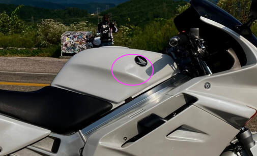 I don't want to talk about it, but…. Shortly after final assembly of Project 39, my personal '93 VFR750, in an instant of inattention, I dropped the bike in the shop. It landed on a carpeted area which mitigated some damage, but the right handlebar moved rearward at impact and dented the freshly-painted fuel tank. This is not acceptable, so I showed my painter, Steve, and after a suitable, well-deserved scowl from him, he determined that paintless dent removal was not an option (no interior accessibility) and he would need to repaint. He's working on another task for me right now, so I took the tank back home and decided to try out an inexpensive tool I'd seen on YouTube — a dent puller kit. 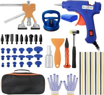 Click on image for Amazon link Click on image for Amazon link These ingenious gadgets use hot glue applied to little tabs of various sizes & shapes, which are glued to the dent and then pulled straight out with a special puller attached to the tabs. The kit also supplies a light-weight hammer & driver with various-shaped plastic tips to drive down any raised spots resulting from the pulling action. With nothing to lose, I began repeatedly glueing/pulling/tapping, watching in amazement as the dent slowly disappeared. Now, this technology is obviously meant for the thin sheet metal used on modern cars, not heavy gauge motorbike fuel tanks. The glue has only so much holding power, and would often pop off at its limit. I probably glued/pulled 30 times before deciding I'd progressed as far as possible on this dent. In the end, I think I got the dent to about 90% removed, but the metal remains a bit "lumpy." Amazingly, the initial impact and all the pulling/tapping never affected the paint, which remains perfectly intact. I will likely still have the tank repaired/repainted, but at least I made the job quicker and easier for my painter. I do think this device would be very effective for automotive use. I tried to photograph the final result, but the camera doesn't pick it up well. If the bike's overall presentation was of average quality, I would accept this repair, but that's not the case with #39. (click on an image to enlarge) Today marks the unofficial mid-point of our winter season here on the upper reaches of the globe. It's a nice reminder that this won't last forever with warmer days to come. Here in the upper midwest we're under a polar blast — it's reading -4°F (-20°C) this morning. But, I'm plugging away at my projects, the shop heater straining to keep the bikes and myself comfortable, Miles Davis' mellow trumpet tones in the background, knowing that in about eight weeks time I'll be looking for the roads to be clear of their residual salt dust, allowing some short test rides.
"And the seasons, they go round and round." 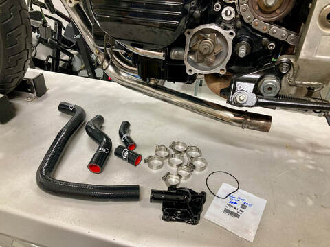 Click on image for the AS3 link Click on image for the AS3 link After receiving several silicone hose sets from AS3 in the UK, I'm able to install the refurbished cooing system components on Project 42. It was nearly two years ago that I sent AS3 an OEM set of RC24/26 coolant hoses as a pattern for them to produce and market replacement hose sets for our old bikes. I fitted the prototype set on Project 41 some months back and they're now in production. They're beautiful items, fit perfectly and look great, especially when you install with their special hose clamps. And they come in colors! This bike is to remain as original as possible…so black it is. (Below) I begin by fitting the refurbished radiator. This rad only required a good cleaning, fin straightening and painting of the fins and front grill cover. These grills are prone to rusting and always seem to need repainting. Everything is bolted in place with the original fasteners, detailed and protected with preservative. Finally, the fan connector is plugged into its harness connection. (Below) Next, I'll install the short hose from the thermostat housing to the engine block. After noting how the clamps are oriented, I simply cut the old hose in half, remove the clamps and pull the two pieces free. This is less of a struggle if the thermostat housing is off the engine, but not necessary. If there's corrosion on the hose fittings, I clean those up with a little sandpaper and slip the new hose & clamps in place. (Below) Now I'll tackle the short hose mating the water pump and chrome inlet pipe. This one is particularly difficult as there's only about 20mm of space to remove/install a 70mm length of hose. Here's a trick I use: Remove the water pump cover (this should be done in any case to inspect the water pump impeller blades). Pull outward slightly on the pump housing which allows the housing to rotate — this provides much more room to remove/install the hose. Slide the hose onto the chrome pipe, rotate the housing back into place, and slide the hose back onto the housing nipple. Before tightening the hose clamps, be sure to align the pump housing's bolt holes. Note: The pump housing can be entirely removed by pulling straight outward, but be sure the oil sump is drained down about a quart or oil will exit through the mounting hole. If you choose to remove the cover and/or pump you'll want to have new o-rings on hand — one for each — available from Honda. (Below) To finish up, I install the powder coated water pump cover with a fresh o-ring gasket, followed by the two large radiator hoses. I like to slide the original hose protector sleeves in place on the new hose — here I have tape holding the upper sleeve in place while the cement cures (I could have cemented it in place on the bench). The lower sleeve will stay in place without cement. 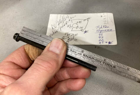 (Right) The water pump/sprocket bolts are varying lengths so I use a cheat sheet I made up years ago to help me remember. If you're not aware, this photo shows the proper way to measure bolt length. 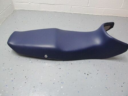 Click on image for the eBay link Click on image for the eBay link Need a replacement seat? Here's a great candidate…but we need to discuss color. This original 2d-gen seat is offered on eBay for $209.75 including shipping to CONUS. I looked over the photos for the usual wear points but didn't find anything. (The following applies to U.S. model bikes) This appears to be in the Mystic Purple color of the R/W/B 1986 750F models. I've always found that the '86 700F2 (Pearl Crescent White bikes) had a different shade of blue, called Denmark Blue, but the current parts diagram shows Mystic Purple for both the 1986 F and F2. Checking with the Honda Motorcycle Identification Guide the '86 F2 seat color is simply noted as "blue." Note that in '87 the white bikes wore black seats and the blue/silver bikes wore gray, so this seat is not a correct color for either '87 model. To add to the confusion, the seller lists the part number stamped on all '86-87 seats, which is no longer a valid part number in any case. So, this seat will fit any '86-87 VFR 700/750, but the color will only correctly match the 1986 bikes — and I still hold that the Pearl Crescent White '86 F2 seats were Denmark Blue, but I could be mistaken. Remember, if you have a passenger seat cowl, that padded cover color will also need to match this seat color. Back to this eBay classified — these seats are getting very hard to come by in serviceable, original condition, much less as nice as this one appears to be. A good cleaning and two applications of a vinyl conditioner should have this looking like new. I use Motul Perfect Seat…. 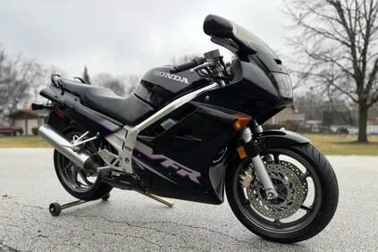 Click on image for the BaT link Click on image for the BaT link SOLD: $3700 One of the rarest of VFRs to spot in the wild, this 1992 750 stands out from the crowd in its menacing Granite Blue Metallic, a unique color in that you'll only really spot the subtle blue/purple metallic when viewed at just the right angle. Otherwise, it appears as black, which itself would be a rare VFR color in the U.S. market. This example shows very well, indicates an amazing 6433 miles and appears in very original condition, right down to the extended rear fender, which is nearly always chopped on these models (including my own). This bike will make a great classic rider or would be a good candidate to bring up a notch with some detailing to several bits which are showing their age, like the upper fork clamp, kickstand, etc. But, overall, this is a very well-preserved 3d-gen which presents much better than its 31 years would indicate, and most of the maintenance heavy lifting has been accomplished. I would say that our buyer has scored a great deal. 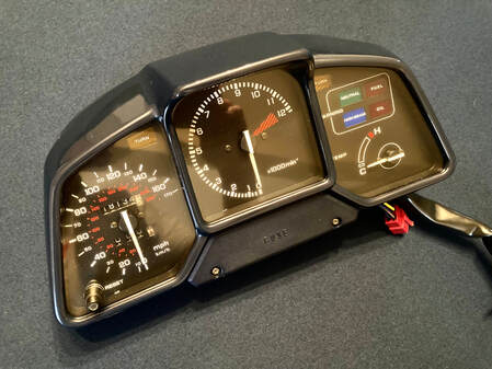 Assembly continues on Project 42. While the instrument assembly was in good mechanical condition, the cosmetics required some attention. The "square" instruments on this 1986 VFR750 won't make sense to us in the U.S. as that model would have been fitted with round-faced gauges. But this is a UK transplant and so we have this dark blue square-face assembly, which would make its U.S. appearance with the '86-87 700cc F2 model. The issues here were that the nacelle was stained and faded over the years, and the lens was beginning to cloud. After disassembly, I was able to gently polish out both with Meguiar's Ultimate Compound. I had to be very careful with the nacelle as each pass would leave blue color on the cloth, meaning I was removing paint, but I eventually got it back to a beautiful gloss finish. The lens clouding turned out to be mostly on the inside surface which also responded well. I finished with a ceramic polish on those surfaces and, after a general cleaning of the rest of the assembly including the fuse connections, it was ready for installation. (Below) When I removed the instrument assembly I disconnected all the wiring connections living behind the headlight fairing. I do this to inspect, clean and "exercise" the brass connectors. While I've done this many times, I still take photos beforehand as a reference during reassembly and refer to the FSM where I discovered that one of the harness bundles had been routed incorrectly on this bike. Honda really helps out here as the connections can only fit with their mate, whether by shape or color. I apply dielectric grease to the connectors and take my time with routing, as I don't want to risk any handlebar binding or chafing. With all the wiring in place I check the handlebar movement and connect the battery to ensure the electrons are flowing correctly. 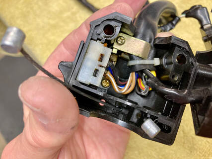 Some of those wire connections originate from the handlebar switch assemblies. I always open these up to inspect for stuff like mud dauber nests or sticky goo from years of mixing dirt and grease. One sign of your assemblies needing cleaning is a sluggish turn signal switch, which this bike had. I spray the insides with aerosol electronic cleaner and re-lubricate with dabs of silicone grease, where appropriate. Remount the assemblies, route the wires and cables, and call these small tasks finished. 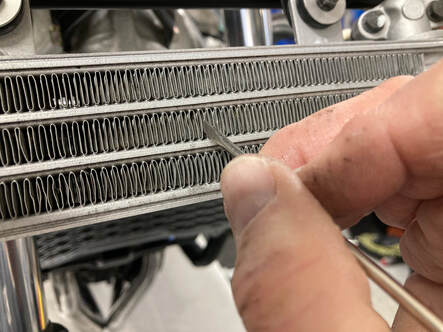 However, before I can think about installing the headlight fairing, I need to address the oil cooler fins. Just like the radiator, I'll carefully straighten the delicate fins as best I can using a small straight-blade screwdriver and dental pick. To clean, the radiators are gently scrubbed with a water-based degreaser and soft bristle brush. Aluminum wheel spray cleaner works well also. Rinse well. Next, I'll deal with the brake components. 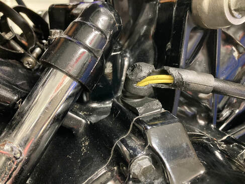 Project 42 has an issue with its stator wiring. As we can see, vermin have seen fit to nibble on the rubber wire guide, located where the wiring exits the engine case. Surprisingly, they didn't touch the wires themselves, which would have brought this repair to another level. While the cover is removable, it's NLA from Honda, but I happen to have an old stator assembly on hand in my parts stash. (Below) Getting the cover off the wire bundle requires removing the end connector (the wires are not removable at the stator). In this case I simply cut off the wire connector, as I'll be hard-wiring the stator/R/R, eliminating the 3-wire connector, a potential weak point in the system. I then pull the old sheath & cover off and slide the replacements into place. (Below) When I make this modification I add about six inches of excess wire to give plenty of room to route the wire bundle and make future cut-and-splice repairs possible. I don't have any yellow wire of the correct gauge so I'll use this red. Today I'll use these handy and effective solder & seal wire connectors. (Below) Here's my completed repair which is then taped and routed. I gently heat the newly taped portion which allows me to bend and shape it behind the fuel pump. This fix is complete.
|
THE SHOP BLOG
|