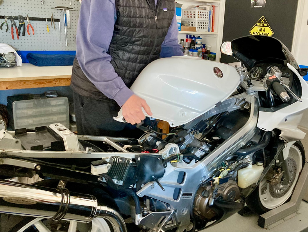
In this tutorial I detail the minimum steps needed to access the carburetors when we're in the position of requiring only carburetor access. This is also the starting point when a more thorough breakdown is desired for additional service — I have a video of that process on the V4 Dreams YouTube channel. There's also a video available detailing the carb removal itself. The procedures below apply, at least in principle, to the other carburetor generations of VF/VFR. For further reference, the Factory Service Manual is also helpful.
The process will require removal of:
• Seat
• Side Fairings
• Tail Cowl
• Fuel Tank
• Carburetors
The process will require removal of:
• Seat
• Side Fairings
• Tail Cowl
• Fuel Tank
• Carburetors
(Below) After seat removal, I begin with the side fairings. Loosen or remove the four Dzus fasteners on the side fairing plus the three fasteners on the bib fairing (the bib will remain in place). The upper bib fastener is not a Dzus, bit should be some sort of annoying plastic pin. I also remove the rear screw fastener on the headlight fairing (pink arrow) to allow some movement to aid in angling the side fairing free — be very gentle separating the side/headlight fairing seam, it is stubborn and prone to cracking. Both sides need to be removed so repeat on the opposite side.

(Below) Next, I'll need the seat cowl out of the way in order to gain access to the fuel pump/filter area on the left side. Remove the four side screws and the two bolts under the seat. The cowl can be propped upward or removed completely by disconnecting the tail and turn signal wiring connectors. (Gen-2; only the fuel pump cover fairing need be removed, the seat cowl remains in place). With the fuel pump accessible, I disconnect the pump's power supply connector; this is done in order to later tune the rebuilt carb set without the fuel tank installed and I don't want the pump running dry. I then use the underseat space as a handy tool shelf.
(click on images to enlarge)
(click on images to enlarge)


(Below) Let's get the fuel tank off. First, remove the tank's rear hold-down nut & bolt which will allow the tank to be raised a bit to help with the following details. With the petcock "off" I disconnect the fuel line at the filter under the seat cowl — have a rag or small container ready to catch the residual fuel in the line and filter, then plug those openings. Also on the left side, I'll need to remove the frame bolt securing the fuel line — the line and bracket will stay with the tank. Lastly, unplug the fuel gauge electrical connector on the right side. The tank removes by sliding rearward, which frees the front mounts, and lifting clear.
We now have access for carburetor removal.
We now have access for carburetor removal.


(Below) Carb removal has been covered here before, but here's the procedure for the Gen-3.
Remove the airbox cover screws and cover, then the base screws, remembering the hidden screw in the front. The base screws are held captive and are of a different design, see photo. In this case the two emissions hoses have been removed from this cover and plugged (circled), if not, then slide those hoses off the cover. Finally, while lifting the base, slide the oil separator hose free from the engine — no need to move the spring clip, the hose will slide off and on with the clip in place.
Remove the airbox cover screws and cover, then the base screws, remembering the hidden screw in the front. The base screws are held captive and are of a different design, see photo. In this case the two emissions hoses have been removed from this cover and plugged (circled), if not, then slide those hoses off the cover. Finally, while lifting the base, slide the oil separator hose free from the engine — no need to move the spring clip, the hose will slide off and on with the clip in place.

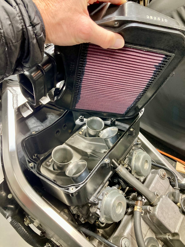


(Below) Remove the choke cable by loosening, but not removing, the clamp and lifting the ferrule free. Leaving the clamp in place prevents it falling into the abyss at reinstallation. Next, remove the fuel line. The line can be very stuck and the "T" fitting is plastic, so proceed gently. Try applying heat or sliding a small blade under the line (without gouging the fitting!). Resist cutting the hose with a blade, also to avoid scoring the plastic fitting. If your line looks original or just old and hardened, seriously consider replacement — it's 10mm or 5/8" fuel line (Gen-2; see Fuel Line Kit on the Products page). Cap the "T" fitting.
Next, slide the idle adjuster free of its bracket, then remove the two screws holding the throttle cable bracket to the carbs, using the slack to remove the two cable ferrules. There's no need to touch the cables' adjustment nuts.
Next, slide the idle adjuster free of its bracket, then remove the two screws holding the throttle cable bracket to the carbs, using the slack to remove the two cable ferrules. There's no need to touch the cables' adjustment nuts.


(Below) Specific to the Gen-3, I'll need to pivot this thermostat housing brace (pink arrow) rearward to provide access to the #3 mounting band screw. The brace is bolted to the engine (green arrow) and to the housing (yellow arrow). First I'm removing the housing screw; here, it's a 5mm allen screw, but yours might be a phillips or hexhead screw. Next, loosen, but don't remove, the 14mm bolt at the rear just enough to provide free play to move the bracket outward and pivot it to the rear, where it can remain.


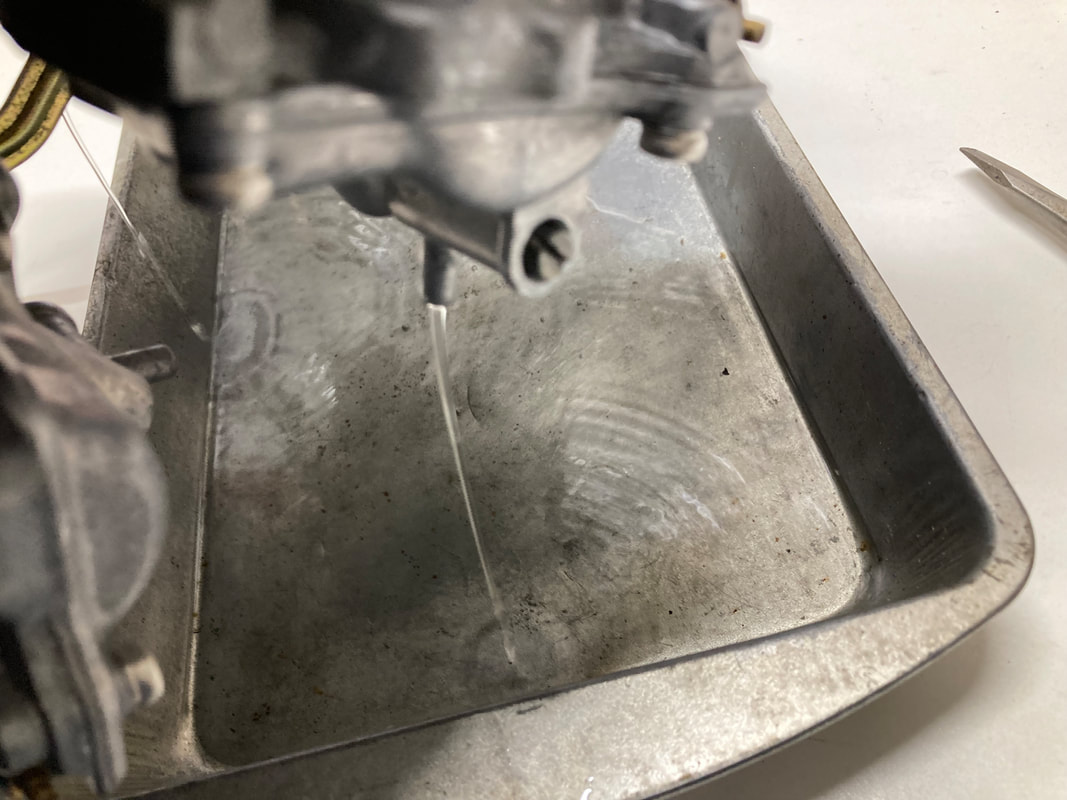
(Below) Next, I can loosen the carb insulators (boots) using a long-shaft JIS screwdriver or 8mm socket. The right side carbs are accessed from the right side, the left from the left side. Loosen only the upper band screws, leave the lowers alone. You don't want to completely remove the bands' screws, so I've learned to make 25 quarter-turns on the tool. I then pry both rear carbs upward to free them, gently levering on the carb bodies, not the choke rod! Once the rears pop free, simply lift upward on the carb set (the fronts will pop free) and carefully lift away from the bike. Finally, drain the carb bowls on the bench and stuff some clean paper towel into the intakes.


Installation goes smoothly by simply reversing these steps. I'm removing these carbs in order to tune/sync a couple sets of rebuilt carbs, so while the shop is warm I install the carb sync adaptors in preparation; see tutorial #19, "Preparing For Carb Sync" on the Maintenance page.
Job done!! That's a lot of wrenching just to get at the carburetors…always makes me wish for the days working on my old BMW airhead.
Job done!! That's a lot of wrenching just to get at the carburetors…always makes me wish for the days working on my old BMW airhead.


 RSS Feed