This is the final tutorial in my carb rebuilding series; Parts one & two can be found in The Shop Blog, December, 2025. You'll also find related tutorials on the Maintenance page.
I'm using a Gen-3 carb set ('90--93), but this is generally applicable to all V4 carburetors.
We left off with the carb set cleaned, inspected and any replacement parts on hand.
Let's get these back together….
I'm using a Gen-3 carb set ('90--93), but this is generally applicable to all V4 carburetors.
We left off with the carb set cleaned, inspected and any replacement parts on hand.
Let's get these back together….
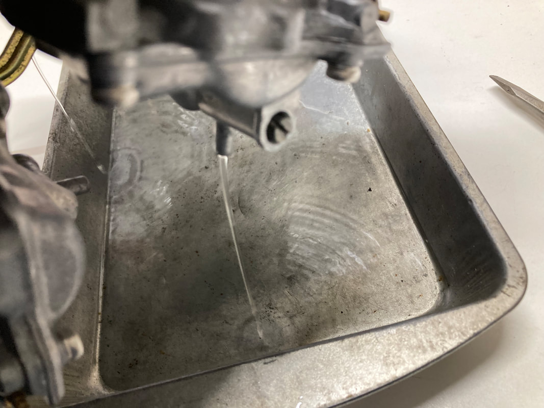
(Below) I'll want to first install any parts which are more accessible with the carbs separated, so I begin with the air cut valve assemblies (Gen-3 and -4 only). First, I set the oval o-ring in place, flat side toward the carb body, then set the diaphragm in place, the small "needle" inserted into the carb body. I've treated the rubber with a light coating of Red Rubber Grease to soften and preserve the diaphragm. With the spring in place I press the cap straight downward, keeping the diaphragm centered, and hold it firmly while installing the first screw — a magnetized screwdriver tip really helps here. These are fiddly assemblies to install due to the firm, wobbly spring, so proceed carefully. Tighten both screws firmly and install the remaining three assemblies.
(click on images to enlarge)
(click on images to enlarge)


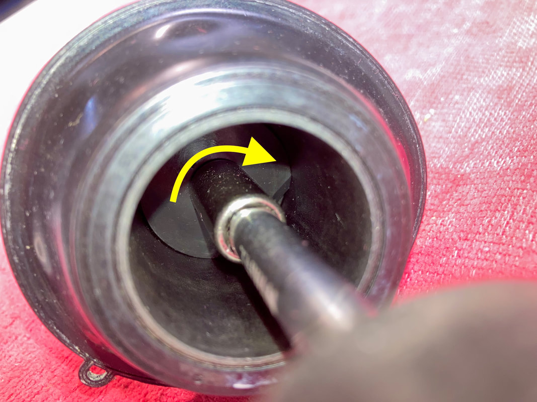
(Below) Next I'll install the fuel mixture (pilot) screws and the enriching (choke) assemblies. I first assemble the mixture screw's spring, then washer, then o-ring and gently seat them fully, then back off 2 1/4 turns (2 1/2 for Gen-2) — this is a good general starting point; an additional quarter turn is a good idea for intake or exhaust modifications. For reference, turning out is more fuel, in is less. Note the black marker on the screwdriver blade; this helps me keep track of rotations.
Note the differing choke shafts and their placement. Assemble the shaft, spring and cap, installing into carbs #1 and 4, gently snugging the cap with a 14mm wrench or pliers. Installing #2 and 3 choke shafts is more involved, assuming you'd chosen to separate those carbs. This is covered in depth in a September 2025 Shop Blog post, "Separating Carburetors, The Easy Way."
Note the differing choke shafts and their placement. Assemble the shaft, spring and cap, installing into carbs #1 and 4, gently snugging the cap with a 14mm wrench or pliers. Installing #2 and 3 choke shafts is more involved, assuming you'd chosen to separate those carbs. This is covered in depth in a September 2025 Shop Blog post, "Separating Carburetors, The Easy Way."


(Below) I'll move on to slide/diaphragm installation next. I first need to install the plastic needle holder into the bottom of the slide (not applicable to Gen-2); this part goes in flat ears first — it's fiddly, but you'll know it's right when the tabs are flush into the bottom recesses (see last photo). I then install the jet needle, using a needle nose pliers and tilting upward to keep the washer on the needle, followed by the spring cap, snugged in place with an 8mm socket. Finally, test that the needle moves freely in & out (a few millimeters) with slight spring pressure.
Note: The Gen-4 slide design is very different, with its own assembly procedure; refer to the FSM.
Note: The Gen-4 slide design is very different, with its own assembly procedure; refer to the FSM.


(Below) Next, I'll fit the assembled slide/diaphragms into their bores. Slide an assembly into its bore, ensuring that the rubber perimeter ridge seats all the way around and the small tab is located correctly (photo 1). Also check that the jet needle has engaged its jet hole correctly (photo 2). I find that keeping the diaphragm raised and holding it with my left middle finger (photos 1 & 4) works best for the next step — insert the long spring, and push downward with the diaphragm cap to engage the cap's tiny raised dowels, all while holding the slide upward; if the cap doesn't seem to positively engage its dowels, try again till it does. It's important that the rubber diaphragm is fully seated in its groove around the perimeter. Holding the slide and cap stationary, install the four cap screws (photo 4); here I'm using an electric screwdriver which makes one-handed screwing easier. Then tighten the four screws (photo 5). Finally, test the slide action by pushing all the way upward and letting it fall on its own — there should be mild resistance going upward and a slight "whoosh" as the slide drops smoothly and gently all the way down to the closed position (photo 6). If you're not getting that action, consider rechecking the diaphragm fitment. If it feels good, proceed to the other three slide/diaphragms.


(Right) I find it easier to fit all four diaphragm caps and then go back and install any ancillary pieces, like the choke cable bracket on #4 carb, shown here. I'm more confident in having installed the diaphragms correctly when only having to deal with the bare screws and not their connecting parts. Here, I'm adding a new screw for the hold-down bracket (it was buggered up) — it's the same screw as the cap screws. Replacement screws are available on the "Products" page.
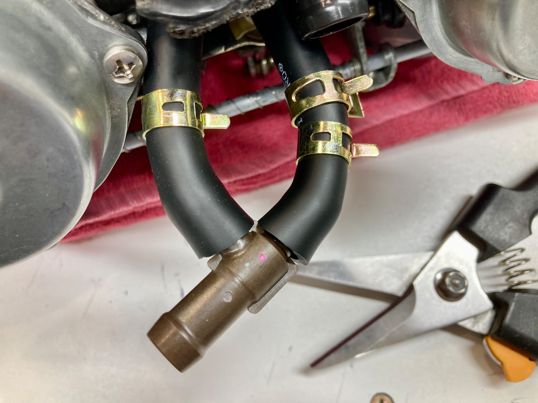
(Below) I'm now ready to install the fuel and vent lines. In the first photo, fire damage actually melted a hole in this vent tube but fortunately I had a spare on hand. If I hadn't had a spare I would have simply put two layers of heat shrink tubing over the area, as these vents will be open to the atmosphere so are not an airtight system. Next, I install fresh fuel tube o-rings and coat all the o-rings with Red Rubber Grease or similar.
I can't demonstrate the tubes' installation in photos, but after an appropriate amount of fumbling about you will eventually get all the tubes in their correct positions — you took photos, right? In any event, photo 3 below shows the correct routing (Gen-3). California-spec carbs have a slightly different-looking vent tube but it installs in the same relative position. On the Gen-3, the hose clip (photo 4) holds the fuel line from carbs #1/3.
NOTE: Gen-2: The choke rod assemblies are installed during the above exercise.
NOTE: For more reference photos of the various generations, see the Maintenance page, end of post #1.


(Right) With everything in place I like to carefully flip the carbs to the engine side and loosely install the center joining bracket which will help hold the tubes in place until I complete the next step: installing the plenum.
(Note: we need this bracket loose enough to allow the carb set to flex enough for the plenum to slip into place)
(Note: we need this bracket loose enough to allow the carb set to flex enough for the plenum to slip into place)
(Below) Here's some tips for preparing the metal plenum for a smooth install. In case you've lost track, on the Gen-2 and -3 this shark fin on the plenum goes between carbs #1 & 3 (photo 1).
I need to verify that all the dowel pins are in place by holding the plenum above the carbs and visually checking every hole has a corresponding pin; some will be in the carbs, some in the plenum (photo 2) — I didn't remove any dowels that were reluctant to remove as they are easily deformed if forced; just leave them in place during the rebuild process. But, to make them easier to slip into place, I clean any accumulated corrosion with a small Dremel wire brush and lubricant the dowels and their openings with a light oil (photos 3 & 4).
For carbs with funnels, like these, it may help if you set each funnel in place on the carb bodies, seeing how the tabs engage, then mark their orientation with a bit of tape or marker (photo 5), then loosely install into the plenum openings with your markers roughly oriented (photo 6). This will help with getting them lined up correctly when lowering the plenum into place.


(Below) Before lowering the plenum in place, verify that all the fuel/vent tubes and lines are still in place and that the carb-to-plenum o-rings are sitting correctly in their grooves. Then lower the plenum onto the dowels, get all four funnels into their slots (photo 1), and work the carbs as flush as possible by hand. Like fitting the fuel/vent lines, this is a juggling act but it can be done. Watch for the fuel/vent tubes to stay in place, they can slip out easily. There will likely be slight gaps between the carbs and plenum due to the tight fit of the dowels, but we'll address that as we snug the screws down.
After a few attempts, and with everything in place, install the plenum brass washers and screws, but just bottom the screws in place, don't force them down yet. When all the screws are bottomed, gently tighten them in an alternating sequence, looking to see that the carbs are gently lowering flush to the plenum — again, don't use force; if it's taking too much effort, something is out of line and causing a bind. I don't bend the washers' locking tabs at this point — I actually wait till the carbs are tested and tuned, just in case they would need to come apart; we don't want to bend those soft tangs more than necessary. NOTE: the washers are available from Honda.
With the carbs seated to the plenum, the carb set is now firmly held together. Flip it over and check that the throttle and choke linkages move freely (photos 3 & 4), if not, figure out why. Visually check that the fuel/vent tubes and lines are still in place, if not, remove the plenum and try again.
Next, I install the underside bracket (or tighten, if already in place). It is important that this bracket naturally lies flush with the carb surfaces (photo 5); we don't want to force the carbs into place with this bracket — if the bracket doesn't lie flush, something is not assembled properly. When all is right with your world, tighten the eight bracket screws (photo 6) and retest the throttle and choke linkages.
Gen-2 and -4, tighten the side screws or nuts.


(Below) Next I install the springs and choke rod assemblies. The two throttle shaft springs slip easily into place (photo 1); the larger between carbs 2 & 4, (Gen-4: between carbs 1 & 3). Next, the sync screws are inserted into the place. I try to make this easier by holding down the relevant butterfly with a finger (just enough to take up its slack) while sliding the spring into place (photo 2) — this can go smoothly or take several tries. I then tighten the sync screws (photo 3) the same amount I loosened them during disassembly, typically 4 or 5 turns (you took notes, right?).
TIP: If you have no base point for the sync screws, you can screw them in till the springs are compressed then turn out four full turns — this will give a starting point for syncing.
These Gen-3 choke rods slide through the outer carb mount, then their spring, then the choke actuating bracket and finally the second carb mount (photo 4). If a rod doesn't want to align with the two mounts, either the carbs are not aligned or the rod is bent — they must be slide freely to operate correctly. Note the correct placement of the bracket's tang on the choke plunger (circled, photo 4). Holding the choke rod in place on the outer carb's choke plunger, I tighten the bracket's screw (photo 5). Give everything a visual inspection and, once again, test the throttle and choke linkages for proper functioning. If anything is binding, it must be addressed before continuing.


(Below) I next install the low speed and main jets. Using a properly-sized screwdriver blade, I snug the low-speed jets in place. Next is the main jet holder; I tighten the holder with a 7mm socket using only firm finger pressure on a 1/4" ratchet or wrench. Then the main jet is screwed firmly into place.


(Below) The float assemblies are next; the float holders (with washers) are firmly screwed tight with a 10mm socket, again using firm finger pressure. Drop the float valve into place and set the float in position, fitting the float's tang under the valve's wire. Slide the pivot pin into place, then check that the float bounces up & down freely. If it's binding, figure out why and fix it.


(Below) Float adjustment is a critical step. With the carb set held vertically, tilt back till the float contacts its spring and settles gently — not fully bottomed, just suspended on the spring. I set all Gen-2 and -3 at 9mm as measured from the carb deck. Here, I have my ruler marked with tape at 9mm for an easy visual picture. Adjust by bending the float's brass tang slightly up or down, as required. I use a dental pick or small straight-blade screwdriver. There's a factory tool available specifically for setting the float height, but this simple method works well for me.


(Below) With everything buttoned up in the float chamber, we can install the float bowl covers. I fit my fresh Viton bowl gaskets followed by the drain screws. I install the covers with their anti-tamper nubs (circled, photo 2) opposite of the factory position, as I've removed the anti-tamper caps from the mixture screws, rendering the whole thing moot. This will allow me to make mixture adjustments if needed, and those nubs won't interfere. Your call, of course.
NOTE: Those anti-tamper caps were EPA dictated and do not need to be installed.
I snug the screws with an electric screwdriver, with final tightening by hand. Replacement screws are available on the "Maintenance" page.
NOTE: Those anti-tamper caps were EPA dictated and do not need to be installed.
I snug the screws with an electric screwdriver, with final tightening by hand. Replacement screws are available on the "Maintenance" page.


(Below) Looking over my workspace, I see only three items left. I test fit the fuel line "T" fitting and trim the lengths as desired to get a useable angle to later join with the fuel line from the pump. Slide the clamps into place, and I always add an extra at the bend point shown, but it's likely not necessary. Next is the idle speed adjuster cable. I screw it into place (note the placement of the spring and washer) and upon contacting the throttle wheel, I screw it two full turns — this gives a ballpark idle speed. Finally, the vent hose can be installed at your option. Its function is essentially to keep water out, so it could be trimmed shorter, reconnected to the emissions hardware downstream, or left off, your choice. I just trim mine below the first curve and angle it downward.


Before these carbs are mated to an engine they're leak tested. Now is the time to find and fix a leak, not after installation. With the fuel bottle filled about 2/3 to give sufficient head pressure, I leave them in the plastic tub for at least 12 hours, or even a few days.
With this final test passed, they can be drained or transferred directly onto the engine for tuning.
TIP: I actually use water for this test, which allows me to safely do this indoors. Also, if a leak is present, there's no gas to deal with while finding and fixing the leak. Just remember to drain the water from the float bowls after leak testing.
I hope this post helps anyone in need. As always, call, text or email me with questions, comments or constructive critiques.


 RSS Feed